
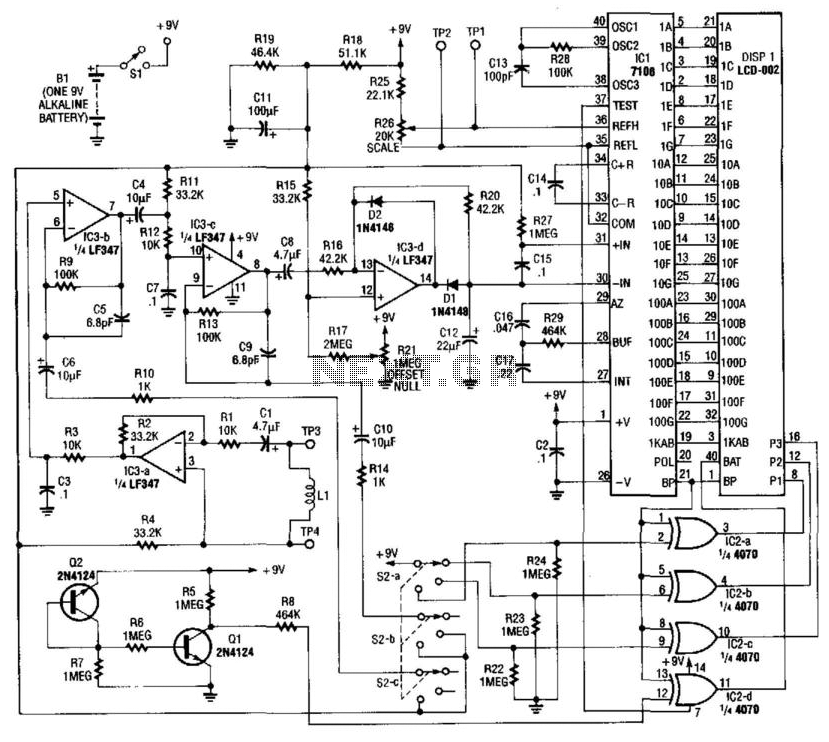
Absolute-Value Meter With Polarity Detector
The circuit operates by utilizing operational amplifiers (op-amps) to achieve the desired signal processing. The first stage of the circuit involves rectification, where the absolute value of the input voltage is obtained. This is typically accomplished using a precision rectifier configuration, which allows for accurate rectification of small signals without the voltage drop associated with traditional diodes.
Following the rectification stage, the circuit employs a comparator or a simple logic circuit to determine the polarity of the input voltage. This is achieved by comparing the input signal against a reference voltage, usually set to zero volts. The output of this stage indicates whether the input voltage is positive or negative, thus providing the necessary sign information.
The final output of the circuit consists of two separate signals: one representing the absolute value of the input voltage and the other indicating the polarity. This dual-output configuration can be particularly useful in applications such as analog signal processing, where both the magnitude and direction of the signal are critical for further processing or control tasks.
Overall, this circuit design is fundamental in various electronic applications, including signal conditioning, measurement systems, and control circuits, where precise voltage analysis is required.This circuit breaks an input voltage signal down into its components: (1) the absolute value and (2) the polarity or ‘sign (+ or ). It will handle direc.. 🔗 External reference
Related Circuits
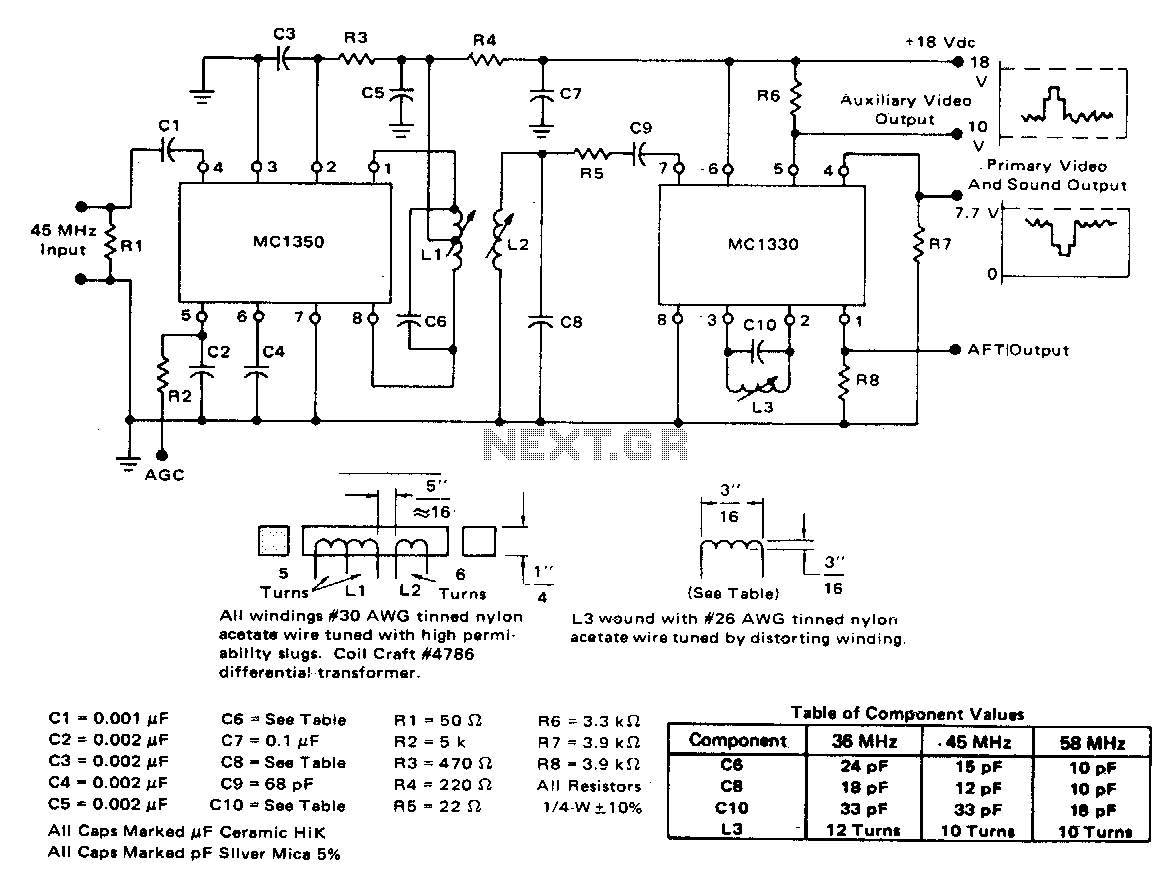
The circuit exhibits a typical voltage gain of 84 dB and an automatic gain control (AGC) range of 80 dB. It demonstrates minimal alterations in bandpass shape, generally less than 1 dB tilt for 60 dB compression. There are...
Using a pickup coil to drive an amplifier (IC3A-B-C-D), this meter circuit can be directly calibrated in field intensity units. R3/C3 and R12/C7 establish a frequency roll-off that compensates for the pickup coil's sensitivity and set a 20 kHz...
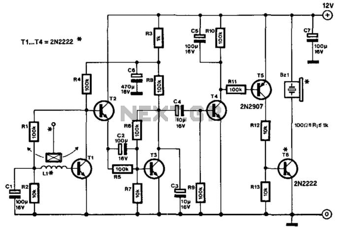
This highly sensitive movement detector is designed using bipolar transistors and operates with a current draw of only 0.3 mA during quiescent conditions. It is primarily intended as a protection device but can also be utilized in specific games....
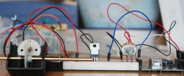
A quick circuit showing how to control the speed of a DC motor with a potentiometer with your Arduino board. Also shows how to use a TIP120 transistor to allow the Arduino control a larger power supply. This circuit utilizes...
This text outlines preliminary plans for a frequency meter designed for a bat detector. The device measures the frequency of the local oscillator in a heterodyne type bat detector, serving as a valuable tool for bat identification. The frequency...
In Fig. 1 A precision DC undervoltage relay switch. The op-amp is wired as a voltage comparator, with a reference voltage applied to pin 2 and the test voltage applied to pin 3: the relay turns on when the...