
Blood pressure sensing circuit diagram BP01-type pressure sensor
The circuit design incorporates a BP01 pressure sensor, which is optimized for blood pressure measurement applications. This sensor's construction ensures minimal noise and high linearity, essential for accurate readings in medical devices. The use of a thick film ceramic chip contributes to the sensor's durability and performance stability, while the nylon plastic packaging protects it from environmental stressors.
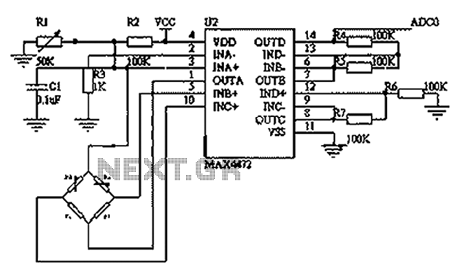
The MAX4472 operational amplifier is selected for its low power consumption, making it suitable for portable applications. The internal architecture of the MAX4472, featuring four op-amps, allows for versatile configurations. In this application, one op-amp is dedicated to providing a constant current to the BP01 sensor, ensuring that the sensor operates within its optimal range, regardless of variations in supply voltage or load conditions.
The differential amplifier configuration formed by op-amps B, C, and D enhances the signal from the pressure sensor by amplifying the difference between the input signals, effectively filtering out common-mode noise and improving the signal-to-noise ratio. The output from this differential amplifier is then conditioned for input to an analog-to-digital converter (ADC0), which digitizes the analog signal for further processing and display in a blood pressure monitoring system.
Overall, this circuit exemplifies a well-engineered solution for accurate blood pressure measurement in portable devices, ensuring reliable performance through careful selection of components and circuit configuration. As shown below, this circuit uses BP01-type pressure sensor and op amp MAX4472.BP01 type pressure sensor is specifically designed for the detection of blood pressure, mainly us ed in portable electronic sphygmomanometer. It uses precision thick film ceramic chip and nylon plastic package with high linearity, low noise and stress of the outside world of small features; the internal calibration and temperature compensation to improve the measurement accuracy, stability and repeatability, in full scale, accuracy of 1%, the zero offset is not greater than 300 V.MAX4472 MAXIMs a four integrated low-power operational amplifier amplifier chip. The system integrated operational amplifier A constant current source connected to provide a constant current of a pressure sensor, and the op amp op amp B C, D constitute a differential amplifier input, single-ended output amplifier circuit, direct input ADC0 DC component of blood pressure monitoring.
Related Circuits

The thermistor RT, along with resistors R1, R2, R3, and variable resistor RP1, creates a temperature measurement bridge. At a temperature of 20°C, the configuration of R1, R3, and the adjustment of RP1 enables the bridge to maintain balance....
If expecting an important visitor but needing to step out for a moment, an electronic doorbell memory can be useful to check if someone rang while away. Although it may not indicate whether the expected visitor arrived, a quick...
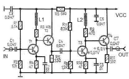
A simple and effective antenna amplifier can be built using the provided circuit diagram. This amplifier is designed for the frequency range of 35 kHz to 150 MHz. It utilizes transistors, offering a low non-linearity of 3 dB and...
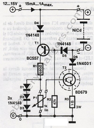
This 24V to 36V linear battery charger is long overdue. While this is an old circuit technique, it is optimized for charging higher voltage lead-acid batteries. The 24V to 36V linear battery charger is designed to provide a stable charging...
This circuit is an ultra-sensitive infrared (IR) receiver designed to control various AC devices via an IR transmitter. It utilizes a phototransistor... The ultra-sensitive IR receiver circuit is engineered to detect infrared signals emitted from an IR transmitter, enabling the...
All electronic circuits were initially built on breadboards. Once the circuits were operational, they were soldered onto perfboards to create a more durable system. A power board was designed to stack two batteries in series, providing access to a...
Warning: include(partials/cookie-banner.php): Failed to open stream: Permission denied in /var/www/html/nextgr/view-circuit.php on line 713
Warning: include(): Failed opening 'partials/cookie-banner.php' for inclusion (include_path='.:/usr/share/php') in /var/www/html/nextgr/view-circuit.php on line 713