
AC input circuit

The AC input circuit is a crucial component in power supply designs, ensuring that the incoming AC voltage is clean and stable for subsequent processing. The fuse (Fl01) serves as a protective device that disconnects the circuit in the event of an overcurrent condition, thus preventing damage to downstream components.
The mutual inductance filter (LF101) is designed to reduce high-frequency noise by utilizing the principle of inductive coupling between its coils. This filter is particularly effective in attenuating electromagnetic interference (EMI) that may be present in the AC supply.
The filter capacitors (CX101, CY101, CY102) play a vital role in smoothing out voltage fluctuations and providing a low-impedance path to ground for high-frequency noise. CX101 is typically placed in parallel with the load to bypass high-frequency signals, while CY101 and CY102 are often used for common-mode noise filtering, ensuring that any noise present on the AC line is effectively shunted to ground.
The overall layout of the AC input circuit is designed to minimize inductance and resistance, which helps in maintaining signal integrity and reducing losses. Proper placement of components is essential to ensure optimal performance, with critical attention given to the grounding and shielding of the circuit to further enhance noise immunity.
In conclusion, the AC input circuit is a well-structured assembly of protective and filtering elements that work together to ensure a clean power supply, thereby enhancing the reliability and performance of electronic devices.AC input circuit AC input circuit AC input circuit is a fuse Fl01, mutual inductance filter LF101, filter capacitor CX101, CY101, CY102 and some other structure into its main f unction is to filter the AC circuit noise and pulse interference, as Figure 2-37 shows AC input circuit.
Related Circuits
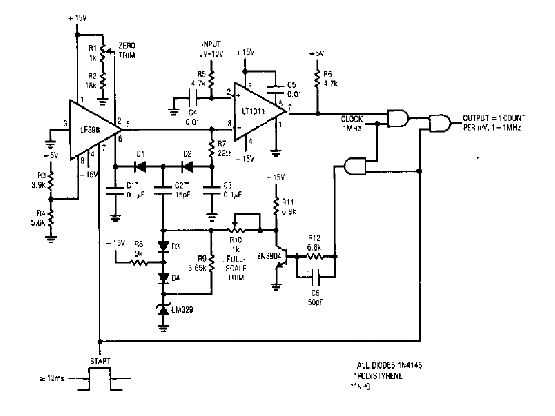
The simple 4-digit converter circuit has an output count of 1, designed to operate within a frequency range of f-IMHz to 10.000. All diodes used in the circuit are IN4146, and the capacitors are made of `POLYSTYRENE` NPO. The...
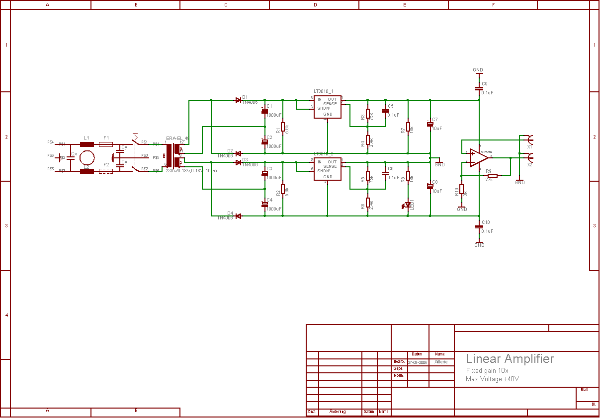
The aim of this project was to develop a linear analogue amplifier designed for laboratory use. This amplifier has to realise a voltage amplification of 10x and is intended to amplify function generator signals for tests. Power supply requirements:...
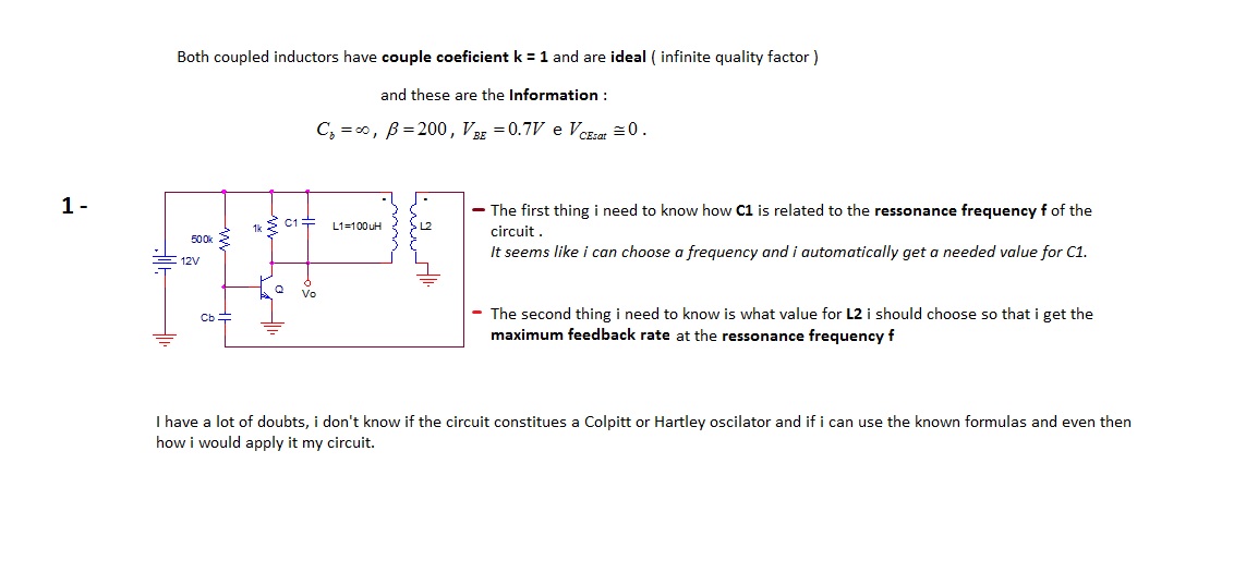
The first thing to understand is how capacitor C1 is related to the resonance frequency f of the circuit. It appears that selecting a frequency allows for the automatic determination of the necessary value for C1. There are uncertainties...
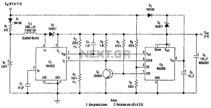
A 9-V wall adapter supplies Vm. IC2 contains a low-battery detector circuit that senses l7IN through resistors R6 and R7. The detector output at pin 7 drives an inverter (Q1), which in turn controls the shutdown inputs of IC1...
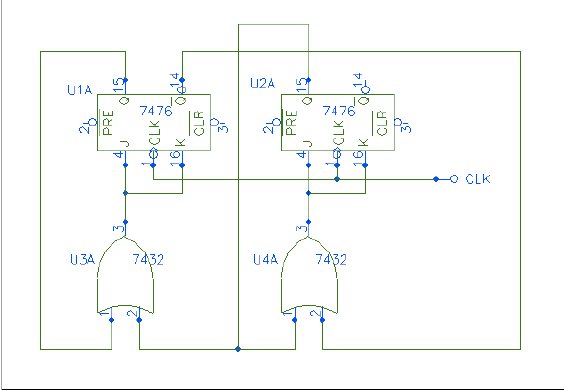
Q1 and Q2 form a table. On the left side, list the four possible states of Q1 and Q2; on the right side, write the values that Q1 and Q2 will assume after the next clock pulse. The table...
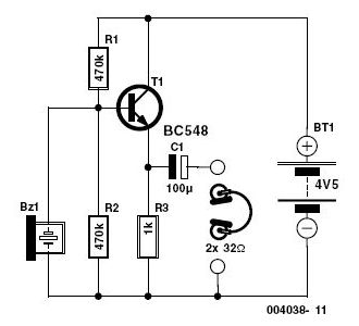
The metronome circuit has been assembled multiple times without success. Two manufacturers of the 555 timer, ON Semiconductor and National Semiconductor, provide circuit designs that differ from the original. In their designs, pins 2, 6, and 7 are not...