
AC Lamp dimmer
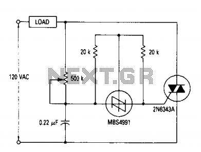
This power controller circuit is designed to effectively manage the brightness of incandescent lamps by utilizing a TRIAC (Q1) as the primary switching element. The TRIAC is capable of handling significant power loads, making it suitable for various lighting applications. The control mechanism involves adjusting the conduction angle of the TRIAC, which directly influences the average power delivered to the load.
The operation begins with the AC voltage waveform. During each positive half-cycle, the TRIAC remains off until it is triggered by the gate current. The gate current is sourced from a capacitor that charges during the initial phase of the AC cycle. Once the voltage across the capacitor exceeds the gate threshold of the TRIAC, the TRIAC turns on, allowing current to flow through the load (incandescent bulbs). The conduction angle, which is the portion of the waveform during which the TRIAC is on, can be adjusted to vary the brightness of the lamps.
The snubber circuit, represented by the RC network across the TRIAC, is critical for protecting the TRIAC from voltage spikes and transients that may occur in the line. This circuit typically consists of a resistor (R) and a capacitor (C) arranged in series. The snubber helps to absorb and dissipate the energy from transient voltages, preventing unintended triggering of the TRIAC. This is essential for ensuring reliable operation and longevity of the TRIAC in the circuit.
Overall, this power controller provides a robust solution for dimming applications, combining effective power management with protective features to enhance performance and durability.A full range power controller suitable for lamp dimming and similar applications operate from a 120 volt, 60 Hz ac source, and can control up to 1000 watts of power to incandescent bulbs. The power to the bulbs is varied by controlling the conduction angle of TRIAC Ql. At the end of each positive half-cycle when the applied voltage drops below that of the capacitor, gate current flows out of the SBS and it switches on, discharging the capacitor to near zero volts.
The RC network shown across the TRIAC represents a typical snubber circuit that is normally adequate to prevent line transients from accidentally firing the TRIAC. The RC network shown across the TRIAC represents a typical snubber circuit that is normally adequate to prevent line transients from accidentally firing the TRIAC. 🔗 External reference
Related Circuits
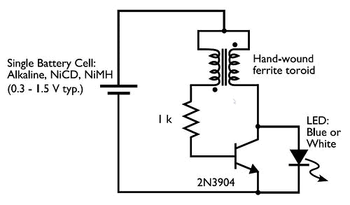
Concerned about darkness? Constructed a basic Joule Thief circuit and wish to advance further? Seeking a striking blue light to impress friends? Introducing the Joule Thief 10x10 LED Lamp! This device operates on one to four AA batteries and...
Savings on electricity bills can be achieved by utilizing alternative power sources. The photovoltaic module, or solar panel, described here can provide a power output of 5 watts. Under full sunlight conditions, the solar panel generates an output voltage...
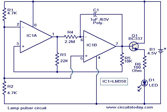
This circuit is designed to gradually pulse an LED or a low-power filament lamp, creating a visual effect where the light transitions from an OFF state to full brightness and then back down to OFF. Such a circuit is...
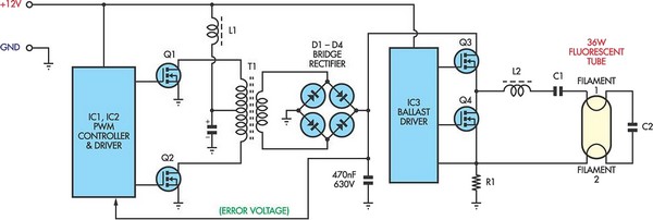
Fluorescent tubes consume significantly less energy compared to incandescent lamps and have a much longer lifespan. Additional benefits include diffuse, glare-free lighting and reduced heat output. Due to these advantages, fluorescent lighting is commonly preferred in commercial and retail...
The circuit below is designed to be used with the bi-directional lamp sequencer shown above on this same page. Two additional transistors are used to increase the current from the 74HCT138 decoder to control 12 volt 25 watt lamps....
The purpose of this circuit is to create a ring in which LEDs or lamps illuminate sequentially. Its main feature is high versatility; a loop containing any number of LEDs or lamps can be built, as each illuminating device...