
AC lights dimmer with triac

This circuit employs a triac-based dimmer design, which is commonly used for controlling the brightness of incandescent lamps. The triac is a semiconductor device that can conduct current in both directions when triggered, allowing for precise control over the power delivered to the light bulb. The diac serves as a triggering device for the triac, ensuring that the triac only conducts when the voltage across C1 reaches a certain threshold. This configuration allows for a smooth dimming effect, as the charge time of C1, which is influenced by the resistance of VR1, determines when the triac will turn on during each AC cycle.
The variable resistor VR1 is critical for fine-tuning the dimming effect. By adjusting VR1, the user can change the resistance in the circuit, which directly affects the charging rate of C1. A lower resistance allows C1 to charge more quickly, leading to more frequent triggering of the triac and a brighter light output. Conversely, a higher resistance results in slower charging of C1, reducing the frequency of triac triggering and dimming the light.
Resistor R1 plays a protective role by limiting the current flowing through VR1, thereby preventing potential damage due to excessive current. The additional components, R2 and C2, are included to mitigate noise and signal disturbances that may arise from external sources or from the circuit itself. This filtering ensures stable operation and improves the overall performance of the dimmer circuit.
To enhance safety and reliability, the entire circuit should be housed in a suitable enclosure, preventing accidental contact with live components and ensuring that it operates safely under normal conditions. Proper heat management is also crucial; if the triac operates at high temperatures, the inclusion of a heat sink is recommended to dissipate heat effectively and prolong the lifespan of the device.This circuit has can to turn down a light bulb arrives at 100W. If Triac there is tall temperature should hold Heat Sink or let off the heat. The Diac be diode that perform be formed encourage or Trigger Diode 2 kinds are way or Bidirectional. The VR1 use for fine decorate turning down fire. Caution this circuit must is in a box closes all the tim e that have the electricity flows through. Operation of the circuit be Lamp L1 is adjusted by adjusting the light of VR1. This will serve to control the speed of charging of C1, Because triac will work. When C1 has charged to the voltage at the triac work. When adjusting the VR1 C1 will charge as little faster lamp is lit. If the adjustment of VR1 C1 will charge very slowly. The little light bulb. Because the triac does not work over the triac during the work. The light bulb will dim down by adjusting VR1. The R1 is placed for protection VR1 prevent damage. The R2, C2 is used to eliminate signal disturbance. Both produced and external circuit. 🔗 External reference
Related Circuits
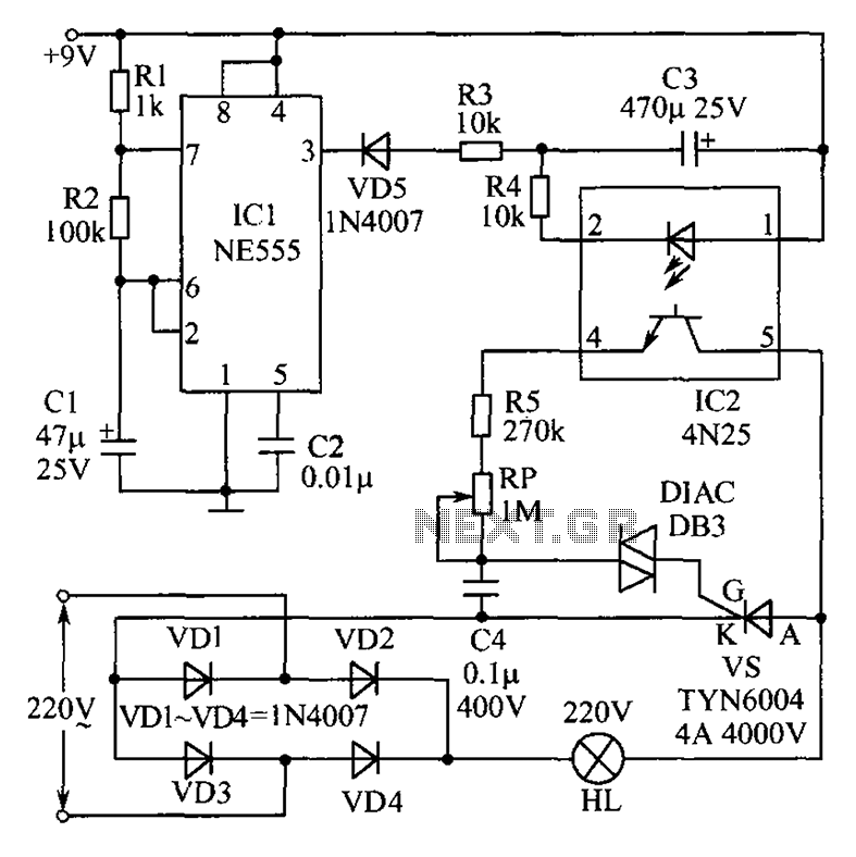
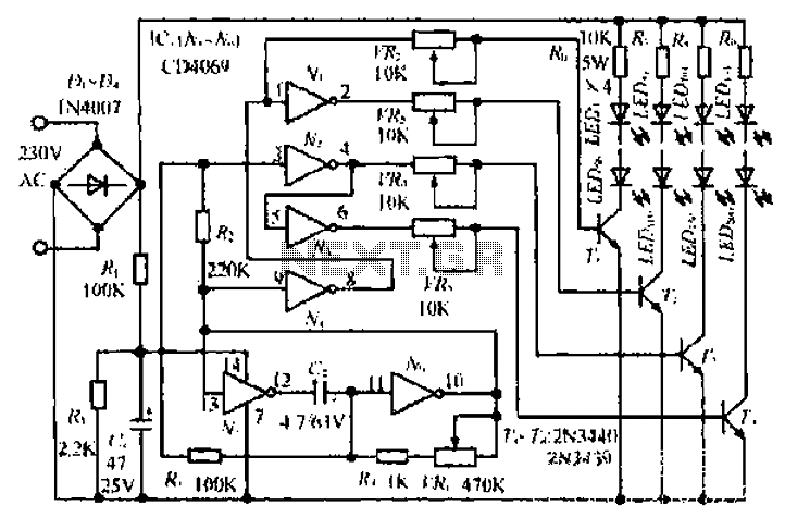
This circuit features an appealing Christmas lights setup. Upon activation, the lights (HL) gradually increase in brightness. Once they reach maximum brightness, they automatically dim, and upon reaching the lowest brightness, they gradually brighten again, creating a smooth transition...
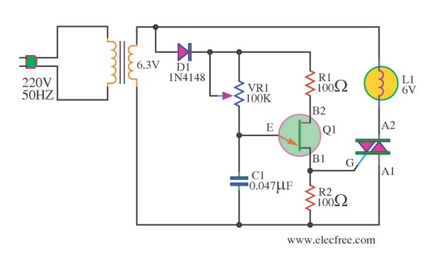
This circuit is an AC dimmer designed for low voltage lamps operating at 6V. While some may not recognize the benefits of this circuit, it serves as an excellent introduction to understanding the operation of a TRIAC. Additionally, it...
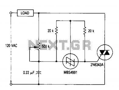
A full range power controller suitable for lamp dimming and similar applications operates from a 120-volt, 60 Hz AC source and can control up to 1000 watts of power to incandescent bulbs. The power to the bulbs is varied...
An air bridge after the bullock Phi Beach in Sichuan utilizes direct beam lights. Control is implemented for six buildings with filtered output at specific voltage levels. The system includes a small 4H servant for pressure control, and components...
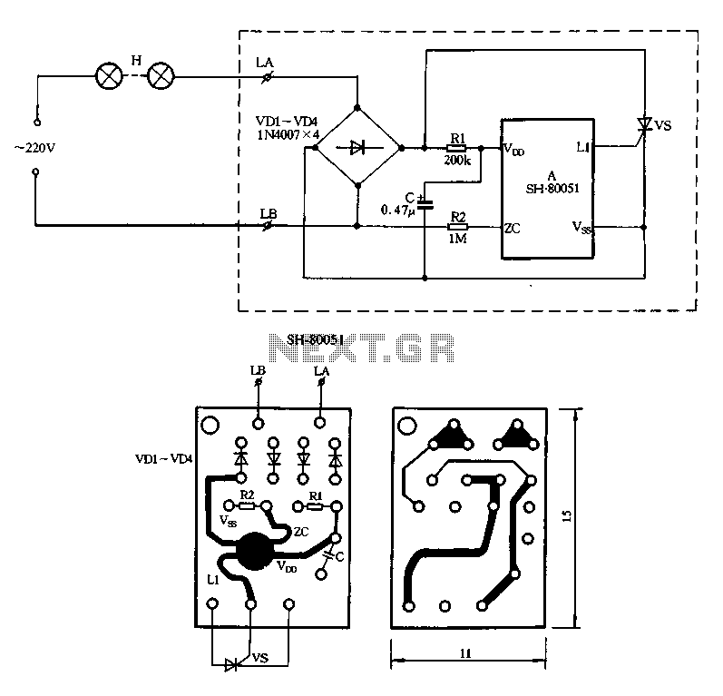
Figure 2-85 illustrates a single-channel SH-80051 flash controller. The SH-80051 chip features four terminals: the positive power supply terminal (VDD), the synchronization input (zc), the negative power supply terminal (VSS), and the drive output (L1). The chip operates with...
Grounding the blue wire at the headlamp switch causes the lights to illuminate, indicating a faulty switch. Continuity of the switch has already been verified. The relay consists of two small terminals and two larger ones. The smaller terminal,...