
AC line circuit diagram of photoelectric switch
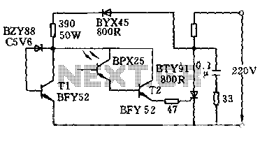
The circuit operates based on light intensity detection, utilizing a phototransistor as the primary sensing element. When ambient light levels rise above the specified threshold of 700lx, the phototransistor conducts, allowing current to flow and activating the BFY52 transistor. This transistor, in turn, generates a trigger pulse that is sent to the BTY91 thyristor, which is responsible for controlling the load current. The thyristor can handle significant current levels, up to 16A, making it suitable for various applications requiring high power.
The BZY88/C5 voltage regulator serves a critical role in maintaining the stability of the trigger circuit. It ensures that the voltage remains within safe limits, specifically below 6V, which is essential for the reliable operation of the components involved. The inclusion of a 390-ohm resistor helps to limit the current flowing into the trigger circuit, further protecting sensitive components from potential damage due to excessive voltage or current.
To prevent damage from negative voltage spikes, a BYX45 diode is positioned in the circuit to block any negative half-cycles from the AC supply. This diode ensures that only the positive half of the waveform contributes to the circuit's operation, which is crucial for maintaining the functionality of the thyristor.
Additionally, the circuit includes protective elements such as resistors and a 0.1uF capacitor that work together to mitigate overvoltage risks. These components help to absorb any transient voltage spikes that could occur during operation, thereby enhancing the overall reliability and longevity of the circuit.
In summary, this circuit is a sophisticated arrangement that leverages light intensity detection to control high-current loads safely and effectively. The careful selection of components and their arrangement ensures that the system operates reliably while providing necessary protections against voltage fluctuations.As shown in the circuit to light when the intensity 700lx above action, this time through the phototransistor and the transistor BFY52 BPX25 to thyristor BTY91 / 800R trigger current. When the light is irradiated on the phototransistor, the trigger pulse is always in the positive half weeks after the starting point occurred about 6 degrees each, by the arithmetic mean of the load flows through the half-wave DC current up to 16A. Regulator BZY88 / C5 and transistor T1 and the resistor 390 is connected to Europe, for limiting the trigger circuit voltage does not exceed 6V.
Diode BYX45 / 800R for blocking the negative half-cycle grid voltage, resistors and capacitors 0.1uF 33 Europe for protecting thyristors against overvoltage.
Related Circuits

The circuit supplies 1 A at +5 V from the -48 V supply commonly used in telephone equipment. More: The National Semiconductor LM2575 is a simple switching regulator. The circuit utilizes the National Semiconductor LM2575, which is a step-down (buck)...

A digital temperature sensor circuit is explained with a circuit diagram. ICs ADC 0804, LM35, and LM317 are used in this digital circuit project. The digital temperature sensor circuit utilizes three primary integrated circuits (ICs): the ADC 0804, LM35, and...

This filter circuit, which utilizes the LM1458 or a similar operational amplifier, has a frequency response ranging from 300 Hz to 3.4 kHz, exhibiting a roll-off of 12 dB per octave outside the passband. Section A serves as the...
This document provides technical details regarding the hardware and software of a complete imaging system that utilizes a fast CCD sensor and a 41 Msample/s A/D converter. This system is capable of acquiring full-frame digitized images at a resolution...
The circuit illustrates a two-stage voltage amplifier that drives a recording level meter. An AC signal input is amplified and rectified, with the resulting DC voltage displayed on the meter. This circuit is compatible with tape recorders or audio...

All ground points in the circuit should be connected to a single point and grounded if possible, or connected to the transformer's 0V marked wire as shown in the circuit. In electronic circuit design, proper grounding is crucial for maintaining...
Warning: include(partials/cookie-banner.php): Failed to open stream: Permission denied in /var/www/html/nextgr/view-circuit.php on line 713
Warning: include(): Failed opening 'partials/cookie-banner.php' for inclusion (include_path='.:/usr/share/php') in /var/www/html/nextgr/view-circuit.php on line 713