
Stabilised amplifier schematic
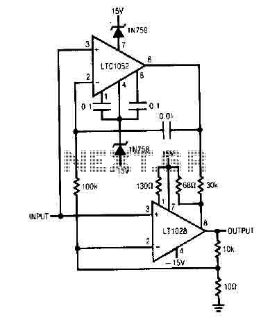
The circuit utilizes the LT1052 and LT1028 operational amplifiers, which are known for their precision and stability. The LT1052 is a low-noise, high-speed operational amplifier, while the LT1028 is a precision, low-drift op-amp designed for applications requiring high accuracy.
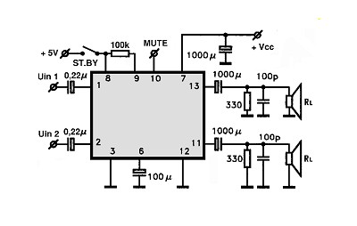
The power supply requirements specify a dual ±15V output with a current capacity of 500mA. This configuration is essential for providing the necessary headroom for the amplifiers, ensuring that they operate efficiently within their specified voltage range. The dual supply configuration allows for both positive and negative signal swings, which is critical for amplifying AC signals or processing differential inputs.
In terms of circuit design, the ideal stabilized amplifier configuration would likely include feedback components to set the gain and bandwidth of the amplifier. Resistors and capacitors would be selected based on the desired frequency response and stability criteria. Proper bypass capacitors should be placed close to the power supply pins of the op-amps to filter out noise and ensure stable operation.
Thermal management is also a consideration, as the LT1028 can generate heat under high load conditions. Adequate heat sinking or thermal relief techniques may be necessary to maintain performance and reliability.
Overall, this circuit design provides a robust solution for applications requiring high-performance amplification, such as audio processing, instrumentation, or signal conditioning, leveraging the strengths of the LT1052 and LT1028 op-amps.It use the LT1052 and LT1028. Power supply should be double with +-15V 500mA. This is a ideal stabilised amplifier. 🔗 External reference
Related Circuits
The current feedback operational amplifier maintains a consistent bandwidth even when the open-loop gain is altered. This characteristic makes it particularly suitable for applications in video signal amplification and the driving circuits of video cables. The accompanying diagram illustrates...
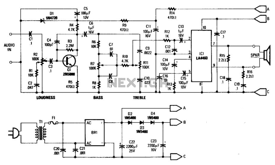
This general-purpose low-power (5 W) audio amplifier is designed to drive speakers ranging from 8 to 12 inches. It utilizes a Sanyo LA4460 integrated circuit (IC) as the audio output component. The circuit features a loudness control, a driver...
The schematic for a monostable multivibrator is shown in figure 3-11. Like the astable multivibrator, one transistor conducts and the other cuts off when the circuit is energized. More: Recall that when the astable multivibrator was first energized, it...
The amplifier circuit utilizing the STK4050 integrated circuit (IC) is known for its robustness and high quality. This article presents a 200-watt power amplifier circuit based on the STK4050. The circuit features an advanced auto wiring diagram with color-coded...
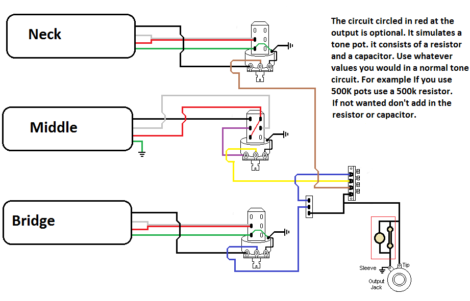
The pickups are connected to individual volume controls that feature push/pull functionality for coil tapping. They are routed to a 5-way switch before reaching the output jack. Additionally, a switch is desired to control the bridge pickup's activation when...

This digital thermometer circuit diagram utilizes a common 1N4148 diode as the temperature sensor. The diode's temperature coefficient of -2 mV/°C is leveraged to create an accurate electronic thermometer. A digital multimeter is employed to display the measured temperature,...