
ac phase control triacs
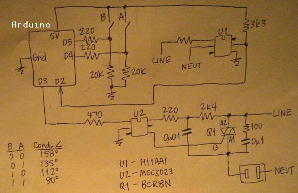
The circuit employs a TRIAC-based phase control dimming system, which is triggered by an Arduino microcontroller. The detection of the zero-crossing point in the AC line voltage is critical for timing the TRIAC's firing. The use of two DIP switches provides a simple method for adjusting the delay angle, allowing for a selection of conduction angles that can be tailored to the specific application. The chosen TRIAC, the BCR8N, is suitable for this application due to its specifications, but the low holding current of LED strings poses a challenge.
The implementation includes a snubber circuit to protect the TRIAC from voltage spikes and ensure stable operation. The Arduino's interrupt capability is utilized to respond to the zero-crossing signal, ensuring that the timing of the gate pulses is precise. This design allows for efficient control of resistive loads, such as incandescent lamps, while also exploring the feasibility of controlling LED lighting. The findings indicate that while traditional incandescent lamps perform well under this control scheme, LED strings require careful consideration of their current characteristics to ensure reliable operation.
In summary, this circuit demonstrates the application of phase control for dimming purposes, highlighting the importance of load characteristics, particularly when transitioning from resistive to low-current LED applications. Further experimentation with additional LED strings or alternative TRIACs may provide insights into achieving the desired performance across various load types.This is an application of what`s known as "random fire" technique for full phase control. The term random iskind ofmisleading. Dimming cannot be effected bytriggering the gateindiscriminately;triggering (firing)must be done synchronised with the line frequency. The line frequency is detected by finding the zero-cross, the point where the line volt age is at or near zero, which occurs with each alternation (half-cycle). The Arduino gets zero-crossing pulses from U1`s output at one of its hardware interrupt pins (D2). The delay angle is selectable via two DIP switches. The default is 1 msec and the DIPs add in binary [i. e. delay time = 1msec + 1, 2, or 3 msec more. ] With that, the conduction angle can be set to 158, 135, 112, or 90 degrees [approx. ]. Obviously, more resolution could be had with more switches, and there`s no obstacle as such in doing so, it`s academic enough, but my objective was not somehigh degree of (or seemingly continuous) variability. This is a research project and thesefew well-definedoptions are sufficient. The zero-cross signal is awaited, its occurrence initiates the Interrupt whereupon the DIPs are read and thereby the delay time determined, then shortly the Gate signal pulses after the appropriate delay time and the process repeats.
As there`s a snubber across the TRIAC and a snubber for the gate, too, I do intend to try it all outwith a fan. That`s my plan. But I confess that I`m squishy on it right now - preferring to bask in the glow of my present success before plunging into a power factor situation.
I have been using "TRIAC", my preference. Should I use Triac when it`s the first word of a sentence and triac otherwise A textbook of mine, "Industrial Solid-State Electronics", uses the latter word form. 26 NOV 2012 The results with a 40W lamp are really good, but managing a string of LED holiday lights leaves much to be desired.
At 90deg, they were practically off. I`m speculating, but I think that the LEDs, being a low-current affair, can`t make the TRIAC`s holding current and end up dropping out prematurely. 26 NOV 2012 (Pt. 2) I ran the LED holiday light string along with a 40W lamp and had much better results. So, it`s the holding current - the LEDlights don`t draw enough (not one string, nor two. ) 27 NOV 2012 So, here`s the last on the LED holiday lights. It came to me that I didn`t need to use a TRIAC at all. Given the low current of these LEDlights, the triac driver (MOC3023) itself is sufficient. The zero-cross reference is still required and the MOC`s logic input has to be kept active for the entire time of the conduction angle.
This is the test "sketch", it`s very coarse, just enough to prove the point. If you need gradual, put more work into it. It doesn`t use the switches, it loops through some values, dwelling at each, and repeating the cycle. I had put the scope away, but I decided to bring it back out and have a look. Despite improved fading over the way it was before, I saw on the scope that it was only conducting on one alternation, asymmetrical.
Then I plugged the 40W lamp in with it and it looked even better than the MOC3023 does. It`s totally textbook with the lamp plugged into it. So, one "strand" isn`t enough to do it with the TRIAC. My strand takes 20ma. My TRIAC (BCR8N) spec has both holding and trigger current of100ma, which means a load of at least 12w. Looks like TRIACs with the lowest holding currents are also of the "sensitive gate" type. There are many Standard types, 400V, 25ma - search Digikey. [Maybe 5 strings would do it to it, but I don`t have that many to confirm. A resistor might fix it, but it won`t present the PTC characteristic (cold = low ohms, hot = high ohms), which it seems would be beneficial at low voltage, but maybe not essential, there has to be a substantial voltage present for the LED string to light up anyway.
] You see that the TRIAC switches off better than the SBS output of the MO 🔗 External reference
Related Circuits
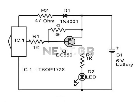
A simple remote control tester circuit with a diagram and schematic using the infrared sensor IC TSOP1738. An LED will blink when infrared waves fall on it, indicating the remote control is functioning. The remote control tester circuit utilizes the...
The remote control transmits encoded signals. Each time a key is pressed, the relevant code is transmitted, usually repeating it many times to ensure reception. This encoded signals travels over a radio or infrared-light beam, to eventually get captured...
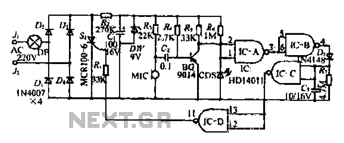
The circuit operates at 380V for air flow. Power is supplied through a step-down transformer, which rectifies the output to 9V DC. When the pump operates correctly, a button labeled 'S' is activated. The circuit utilizes a TWH8778 component....
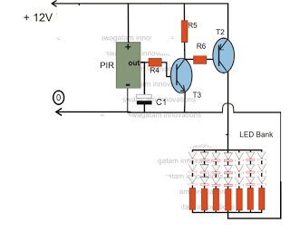
The circuit is an LED driver that responds to ambient light as well as the presence of an intruder, varying its illumination accordingly. Additionally, it includes an ambient light sensor to turn the LEDs on and off, and a...
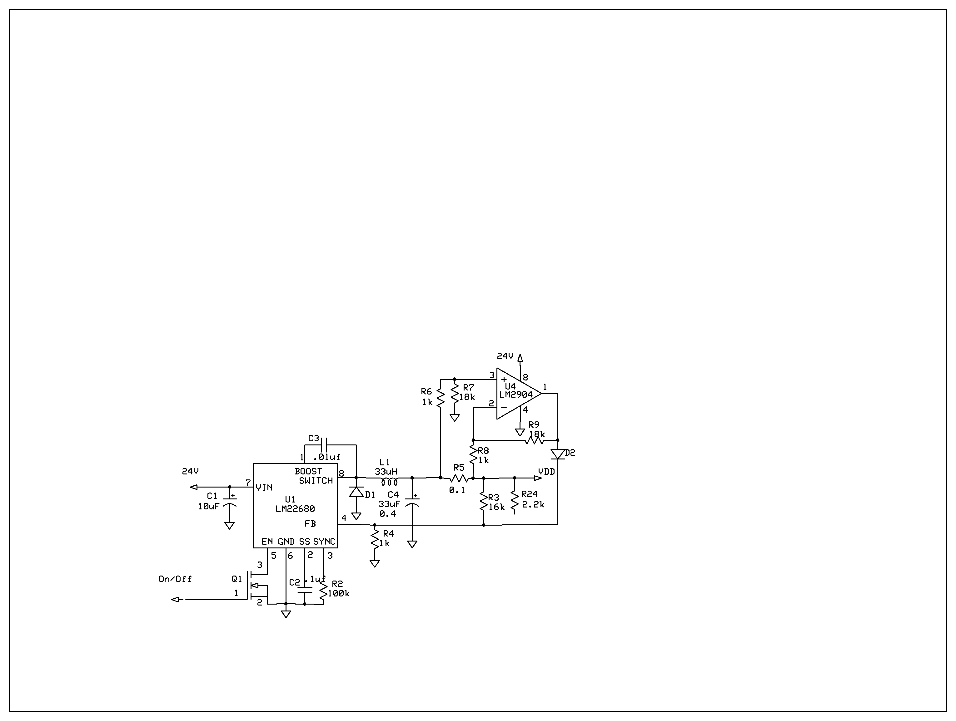
The product requires a voltage-controlled, current-limited power supply. Various switcher chips have been used with an op-amp to provide feedback for a current sense voltage to the feedback pin. Currently, an LM22680 is in use, but it has shown...
Tone Control. Parts: Total Quantity of Parts: Substitutions C1, C3, C5, C7, C15, C16 - 6 pieces of 2.2µF Electrolytic Capacitors; C2, C6 - 2 pieces of 0.05µF Ceramic Capacitors. The tone control circuit is designed to adjust the frequency...
Warning: include(partials/cookie-banner.php): Failed to open stream: Permission denied in /var/www/html/nextgr/view-circuit.php on line 713
Warning: include(): Failed opening 'partials/cookie-banner.php' for inclusion (include_path='.:/usr/share/php') in /var/www/html/nextgr/view-circuit.php on line 713