
AC Power Monitor
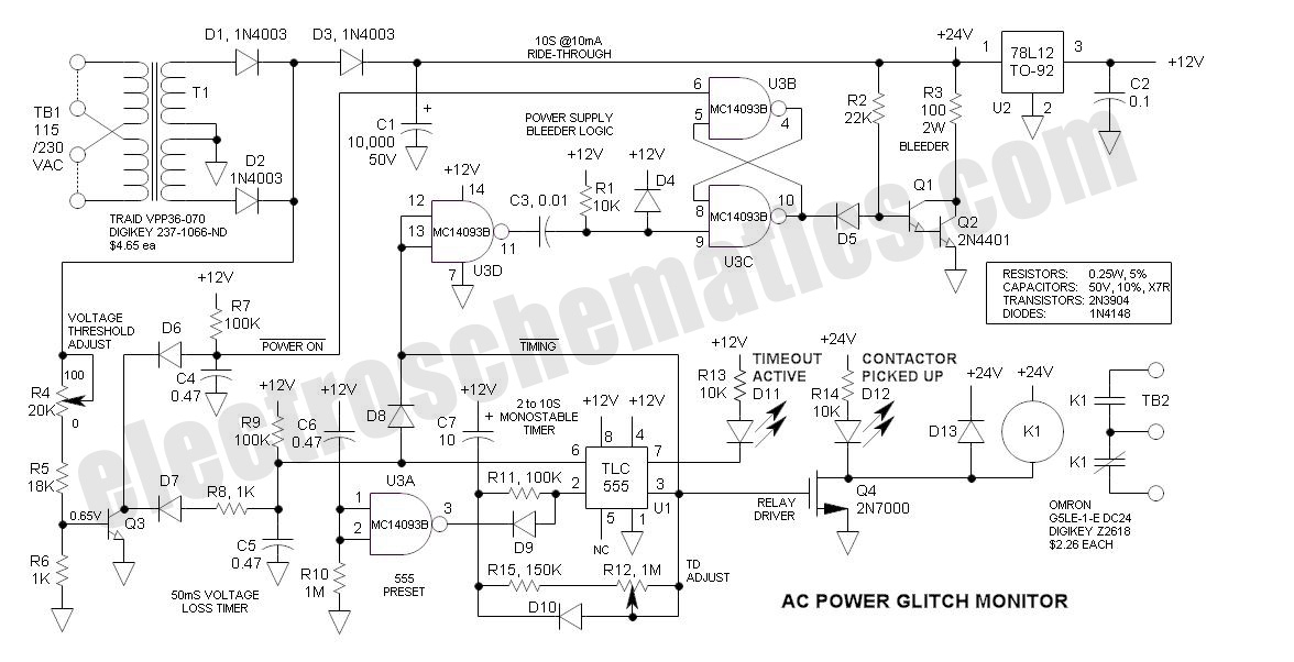
This AC Power Monitor circuit is designed to ensure reliable operation of sensitive industrial equipment during power interruptions, utilizing robust components and configurations to maintain functionality even in the absence of external power. The combination of a large filter capacitor, a CMOS latch, and a reliable timer ensures that the system can handle transient power losses effectively, providing a practical solution for industrial applications. The choice of components, such as the MC14093 and TLC555, further enhances the circuit's reliability and efficiency, making it suitable for environments where power stability is critical. Proper calibration and adjustment of the resistors and capacitors are essential for optimal performance, ensuring that the system accurately detects voltage anomalies and protects connected equipment from unintended restarts.This AC Power Monitor continuously watches the AC power line voltage for both under-voltage and missing cycles. When it detects a total of 5 or 6 consecutive missing half-cycles (50mS, 50/60HZ), it drops a relay and starts a timer.
A power contactor is slaved to the relay contacts. Its purpose is to protect power-loss sensitive industrial equipmen t from brief power glitches by preventing immediate restart. After the specified time delay (2 to 10S), the equipment may automatically restart. Although this may seem like a simple task, note that the condition sensed is the absence of a periodic signal and that the timer may or may not have external power available. electroschematics. com is not really into industrial controls, but this may be the beginning ”this is where I spent most of my life.
This function could also be performed by a PLC (programmable logic controller) with a UPS (unterruptable power source), but such would be expensive and consume additional panel space. Key to this functioning properly is its power-loss ride-through capability. Note that this circuit continues to time out even after the power is interrupted. To run the circuitry for the entire time period, energy is stored in a large filter capacitor (10, 000uf).
That way if the power resumes during the timeout period, the timer remains alive and functioning so that the sensitive equipment may not restart. At the end of the timeout period, the bleeder circuit kicks in to dump the remaining charge. A 4000 series CMOS latch consisting of U3B & U3C is set by the positive transition of U1-3. Should the power resume while the capacitor is bleeding down, the latch is reset via the signal at the collector of Q3 so that the bleeder driver Darlington (Q1 & Q2) turns off.
When all of the charge is dissipated by the bleeder resistor (R3), the circuit is free to immediately restart and again monitor voltage glitches. The MC14093 is a good choice for the power monitor application. It has Schmitt trigger inputs for handling slow input signal transitions, and may be powered by the 12V Vcc.
It is identical in pin-out to the more common CD4011. Note that the CD4011 should also function acceptably, but I did not try it in the circuit. The timer is the good old 555 (actually, it is the TLC555 due to its low quiescent current). It is configured as a monostable multivibrator that is triggered via a positive voltage at U1-6. To assure that the internal latch of the 555 is set in the proper state during power-up, C7 works against Vcc (rather than common) and U1-2 is held low for 0. 5 sec via U3A, C6 and R10. The timeout period may be increased substantially by increasing the size of the timing capacitor C7. Note that C1 must be adjusted likewise to provide additional ride-through. 60 seconds is not unreasonable. Note that the cathodes of D1 & D2 are unfiltered ”this is necessary for rapid sensing of power loss ”a filter capacitor would tend to hold up the voltage thus interfering with the voltage loss timer.
The filter capacitor (C1) is isolated via D3. The Vbe of Q3 (0. 65V) is the voltage threshold comparator. This voltage is multiplied by the ratio of (R4, R5 & R6) to R6. The function of the voltage threshold comparator is to keep C5 discharged. At each line voltage zero-crossing C5 charges slightly, but requires a full 50mS to reach the threshold of U1-6. Should the voltage remain below the threshold of Q3, C5 starts to charge significantly ”if 5 or 6 half-cycles are lost in succession, the voltage across C5 charges to the 8V threshold of U1-6 and triggers the timer.
Proper adjustment of R4 is required. To do so, connect a Variac to the power terminals and reduce the voltage to the desired AC threshold voltage (e. g. 170VAC). Then increase the value of R16 until the LEDs change state. 🔗 External reference
Related Circuits
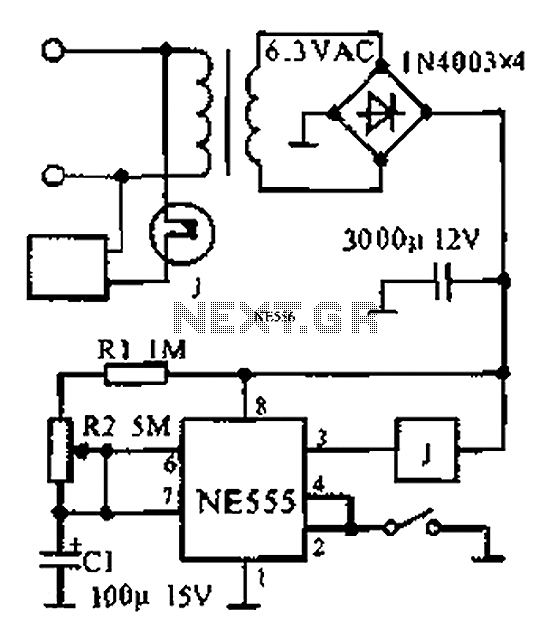
The provided information indicates that when the power supply operates between 0 to 1 hour, an AC circuit diagram is established using a 555 timer configured as a one-hour timer. The relay utilized is a J 212 IRC MR312C...
An alternative method for utilizing operational amplifiers (op-amps) to regulate a power supply is illustrated below. The power transformer necessitates an additional winding to provide the op-amps with a bipolar voltage of +/- 8 volts. This negative voltage is...
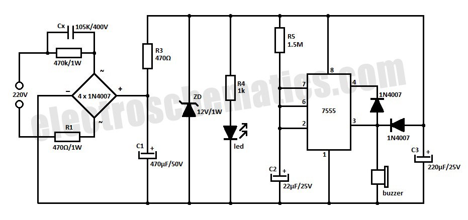
This is a simple power resumption alarm circuit that can be installed within the switch box. It emits beeping sounds when power is restored following a power failure. The power resumption alarm circuit is designed to provide an audible alert...
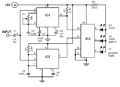
The ability to identify which sections of the tape are unrecorded and which contain recorded data can significantly enhance the efficiency of locating a specific program. This circuit employs a tone decoder IC 567 in conjunction with a timer...
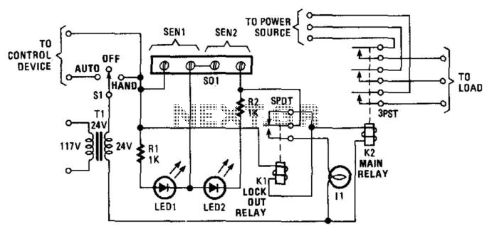
Relay K1 features a low-impedance coil, while Relay K2 is equipped with a high-impedance coil. When a sensor opens, current flows through the coil of K1, activating it. This action opens the contacts of K1, thereby preventing the reclosure...

This is a single-zone alarm system featuring independently adjustable Exit, Entry, and Siren Cut-Off timers. It is compatible with standard normally-closed input devices such as magnetic-reed contacts, foil tape, and passive infrared sensors (PIRs). A mains power supply can...