
variable voltage and current power supply
The described power supply regulation circuit employs operational amplifiers for precise voltage control and current limiting. The configuration begins with a transformer that provides a dual winding output, delivering both positive and negative voltages necessary for the op-amps. The op-amps utilize these voltages to maintain stable output levels and to monitor the current flowing through the load.
A critical component in this circuit is the 500-ohm potentiometer, which serves as a variable voltage divider. The wiper of the potentiometer is connected to the op-amp's non-inverting input, allowing for dynamic adjustments based on the load conditions. The op-amp's feedback mechanism ensures that the output voltage remains stable even as the load varies.
Current limiting is accomplished through a low-value resistor placed in series with the negative supply line. This resistor enables the detection of voltage drops that correspond to the load current. As the current increases, the op-amp adjusts its output to control the base current of the 2N3053 transistor, which acts as a driver for the larger 2N3055 pass transistor. This arrangement allows for effective regulation of the output current, preventing excessive current flow that could damage the circuit components.
Thermal management is also a crucial aspect of this design. The TIP32 and 2N3055 transistors must be mounted on heat sinks to dissipate the heat generated during operation, particularly under high load conditions. The calculations for heat dissipation are essential for ensuring the longevity and reliability of the components. By adjusting the output voltage and monitoring the load current, the circuit can be optimized for various applications while maintaining safe operating temperatures.
Overall, this power supply regulation circuit exemplifies the versatility of op-amps in power management applications, combining effective current limiting with adjustable output voltage capabilities.Another method of using opamps to regulate a power supply is shown below. The power transformer requires an additional winding to supply the op-amps with a bipolar voltage (+/- 8 volts), and the negative voltage is also used to generate a reference voltage below ground so that the output voltage can be adjusted all the way down to 0. Current limit ing is accomplished by sensing the voltage drop across a small resistor placed in series with the negative supply line. As the current increases, the voltage at the wiper of the 500 ohm pot rises until it becomes equal or slightly more positive than the voltage at the (+) input of the opamp.
The opamp output then moves negative and reduces the voltage at the base of the 2N3053 transistor which in turn reduces the current to the 2N3055 pass transistor so that the current stays at a constant level even if the supply is shorted. Current limiting range is about 0 - 3 amps with components shown. The TIP32 and 2N3055 pass transistors should be mounted on suitable heat sinks and the 0. 2 ohm current sensing resistor should be rated at 2 watts or more. The heat produced by the pass transistor will be the product of the difference in voltage between the input and output, and the load current.
So, for example if the input voltage (at the collector of the pass transistor) is 25 and the output is adjusted for 6 volts and the load is drawing 1 amp, the heat dissipated by the pass transistor would be (25-6) * 1 = 19 watts. In the circuit below, the switch could be set to the 18 volt position to reduce the heat generated to about 12 watts.
🔗 External reference
Related Circuits
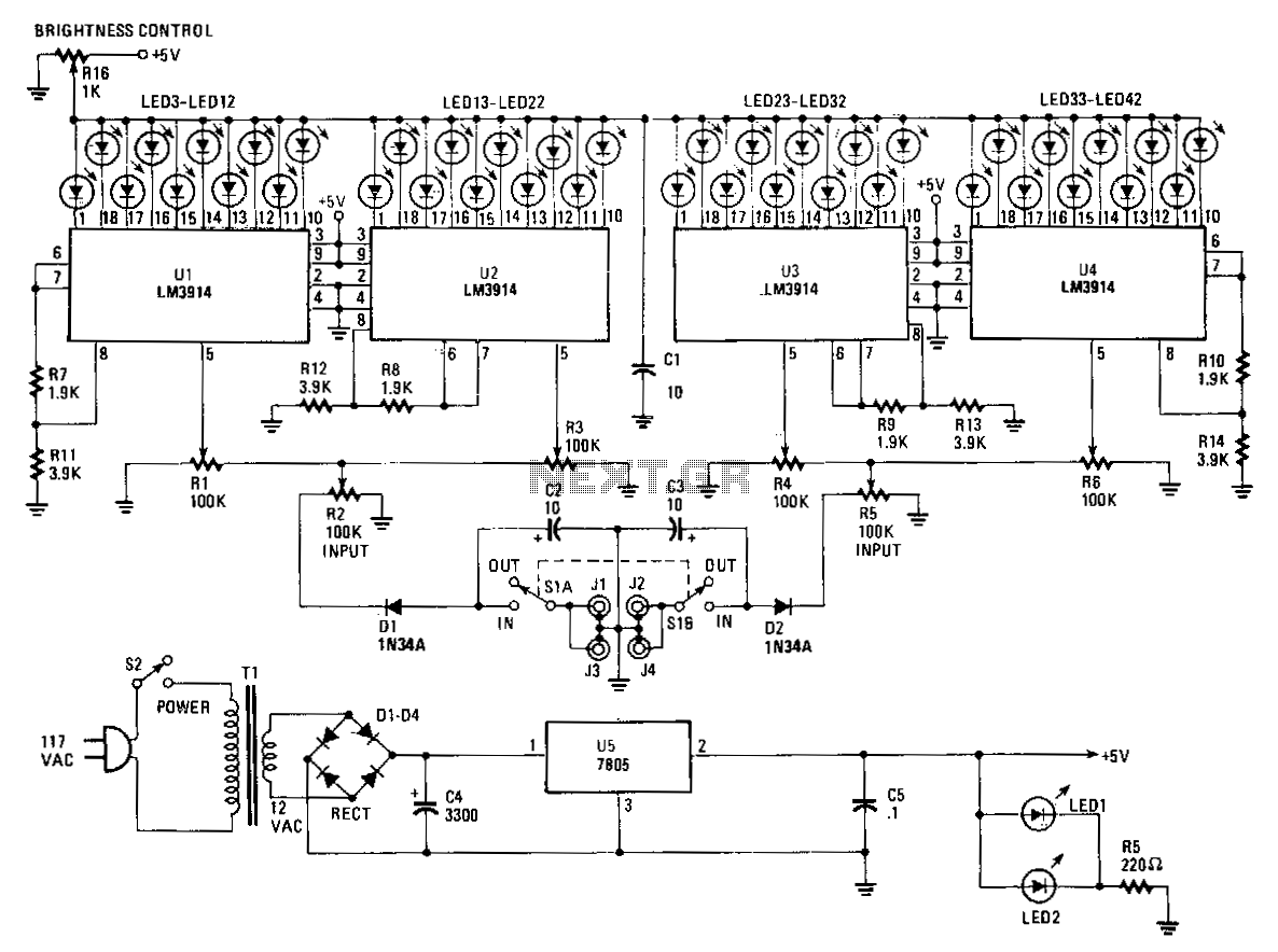
The Stereo Power Meter consists of two identical circuits and a power supply. Each circuit features two LM3914 display chips, which include 10 voltage comparators, a 10-step voltage divider, a reference voltage source, and a mode-select circuit that allows...
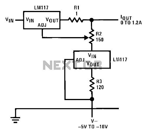
This circuit illustrates an adjustable regulator configuration that incorporates a voltage regulator. In this design, the LM117 regulator is utilized instead of the LM113 diode for reference. Both regulators necessitate a negative supply to function correctly with respect to...
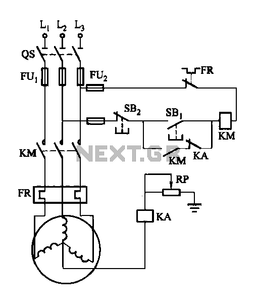
A potentiometer (RP) is utilized for adjusting the operating voltage of the relay (KA) to ensure that the motor operates normally, especially when the relay (KA) does not function reliably during the action phase. The circuit involves a potentiometer...
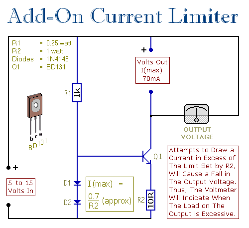
This circuit allows setting a limit on the maximum output current from a power supply unit (PSU). It is particularly useful when powering up a project for the first time or conducting a soak test. By establishing an upper...
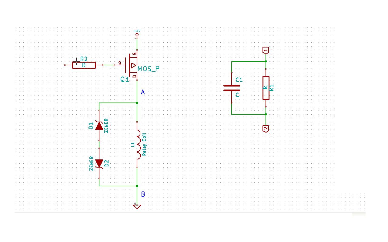
Although this may be a basic question, there is still some struggle with it. In this schematic, two zener diodes D1 and D2 are connected back-to-back across relay coil L1. The breakdown voltage (BVds) is -30V for Q1. The...
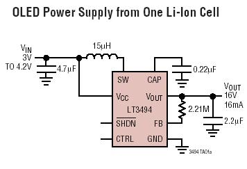
The LT3494 and LT3494A are low-noise boost converters that integrate a power switch, Schottky diode, and output disconnect circuitry. These devices utilize an innovative control technique that results in minimal output voltage ripple and high efficiency across a broad...