
AC-SSR application circuit
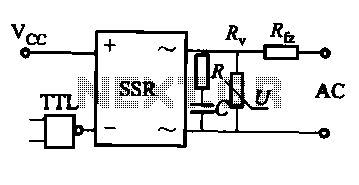
The AC solid-state relay (AC-SSR) is an electronic switching device that utilizes semiconductor components to perform the switching operation, eliminating the mechanical parts found in traditional electromechanical relays. This results in improved reliability, faster switching times, and a longer operational lifespan. The basic application circuit for the AC-SSR typically involves a control input that activates the relay, allowing it to conduct AC power to the load.
The TTL drive SSR circuit (Figure b) employs a Transistor-Transistor Logic (TTL) signal to control the relay. TTL circuits are known for their high-speed operation and low power consumption, making them suitable for interfacing with microcontrollers and digital systems. This configuration typically includes a series resistor to limit the current into the input of the SSR, ensuring that the control signal is within acceptable levels for reliable operation.
In the CMOS driver circuit (Figure c), Complementary Metal-Oxide-Semiconductor (CMOS) technology is utilized to provide a high input impedance and low power consumption. This type of driver is particularly advantageous in battery-powered applications where energy efficiency is critical. The circuit may include pull-up or pull-down resistors to stabilize the input signal and prevent floating states.
The thyristor drive circuit (Figure d) uses thyristors to control the AC load. Thyristors are semiconductor devices that can handle high voltages and currents, making them suitable for heavy-duty applications. The circuit typically includes a gate control mechanism to trigger the thyristor, allowing it to switch on and off in response to the control signal. This type of drive is often employed in applications requiring precise control of AC power, such as motor control and lighting systems.
Overall, the various drive circuits for the AC solid-state relay provide flexibility in design and application, catering to different operational requirements and system architectures.About solid (body) relay AC solid state relay (AC-SSR) of the basic application circuit shown in Figure (a) below; With TTL drive SSR circuit is shown in (b) below; SSR with CMOS driver circuit is shown in (c) below; SSR thyristor drive circuit shown in (d) below.
Related Circuits
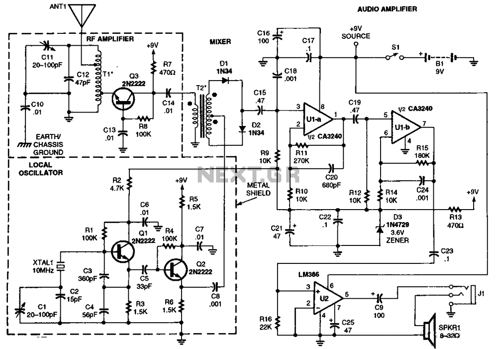
The RF amplifier Q3 connects to diodes D1 to D4 within the mixer. Transistors Q1 and Q2, through transformers T1 and T2, facilitate the injection of liquid oxygen at 10 MHz for diodes D1, operational amplifier U1A, and U1B....
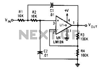
The circuit presented has a cutoff frequency of approximately 1 kHz. The resistors R1, R2, and capacitors C1, C2 can be adjusted to achieve any desired frequency. The circuit is designed as a filter, likely a low-pass or high-pass filter,...
Check the three-phase motor with broken bars as shown in the inspection circuit for the three-phase motor with broken bars. The inspection circuit for a three-phase motor with broken bars is designed to diagnose and evaluate the condition of the...
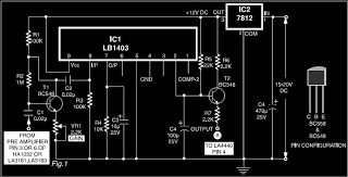
This is a circuit diagram for automatic muting in audio systems utilizing the IC LB1403. The output from a pre-amplifier, such as the LA3160, LA3161, or HA1032, is connected to the base of the amplifier transistor BC548 (T1). A...
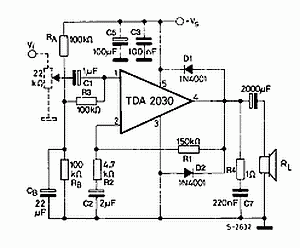
The TDA2030 is a monolithic integrated circuit in a Pentawat® package designed to function as a Class AB audio amplifier. It typically delivers up to 14 watts of output power (with a distortion rate of 0.5%) at 14V with...
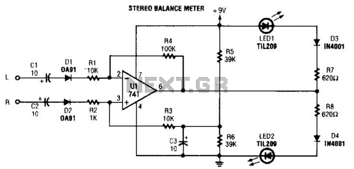
When the L and R signals are equal, no output is present from U1, and pin 6 is at a steady 4.5 V. Unbalanced audio causes the LEDs to vary in brightness, which indicates a difference that corresponds to...