
Stereo Balance Meter Circuit
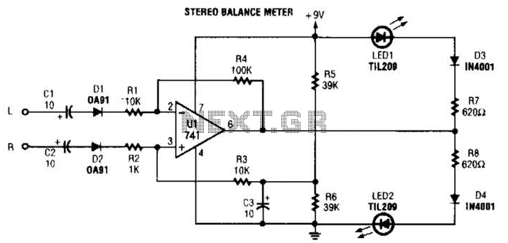
The described circuit operates as a signal balance indicator, typically used in audio applications to monitor the equality of left (L) and right (R) audio signals. The operational amplifier U1 plays a crucial role in this setup. When the L and R signals are equal, the output from U1 remains inactive, resulting in no output signal. Under these conditions, pin 6 of the operational amplifier stabilizes at 4.5 V, indicating a balanced state.
In scenarios where the audio signals are unbalanced, the circuit responds by varying the brightness of connected LEDs. This variation in brightness serves as a visual representation of the degree of imbalance between the left and right audio channels. A greater disparity in signal levels will lead to a more pronounced difference in LED brightness, allowing users to easily identify issues in audio balance.
The circuit may include additional components such as resistors and capacitors to filter noise and stabilize the voltage levels. Proper selection of these components is essential to ensure the circuit's responsiveness and accuracy in detecting signal imbalances. Furthermore, the use of a dual power supply may be necessary to provide the required voltage levels for optimal operation of the operational amplifier.
Overall, this circuit serves as an effective tool for audio engineers and technicians to maintain proper audio balance, enhancing the listening experience by ensuring that both channels are equally represented. When L R signals are equal, no output is present from Ul, and pin 6 is at a steady 4.5 V. Unbalanced audio causes the LEDs to vary in brightness, which causes a difference that corresponds to unbalance between channels. 🔗 External reference
Related Circuits
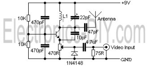
The video transmissions from this unit can be received on a small portable, tunable, and battery-operated TV set, similar to those found in flea markets. The described unit is capable of transmitting video signals that can be captured by compact,...
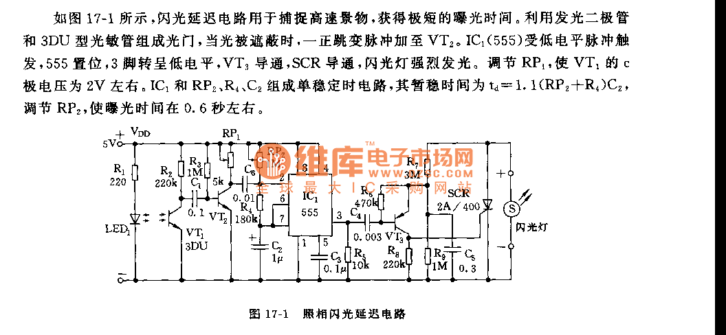
As shown in figure 17-1, the camera flash delay circuit is designed to capture high-speed scenes, allowing for very short exposure times. The light gate consists of a luminous diode and a 3DU type photosensitive tube. When the light...
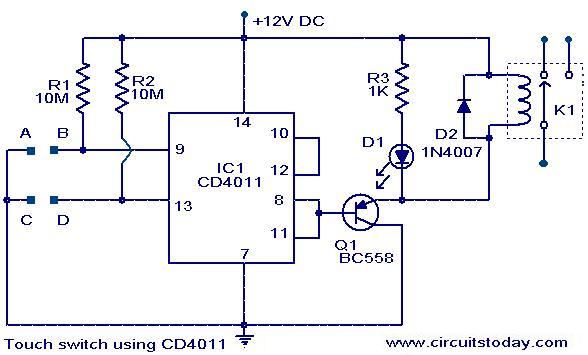
The following circuit illustrates a Touch Switch Circuit Diagram. This circuit is based on the CD4011 IC. Features include R1 and R2, which are the logic gates of the circuit. The Touch Switch Circuit utilizes the CD4011 integrated circuit, which...

This multimeter was designed to measure output voltage and current in a PSU, where the current sense shunt resistor is connected in series with load at the negative voltage rail. It needs only one supply voltage that can be...

When an alarm or notification is needed after ten minutes, the circuit illustrated below can be utilized. This circuit is essentially a monostable multivibrator based on the IC NE555. When the reset push button is pressed, the green LED...
A monostable multivibrator using the IC CD4538 is a precision device that functions as a monostable/astable multivibrator and is designed to avoid false triggering. This IC is suitable for various applications requiring precise timing cycles. The CD4538 offers improved...
Warning: include(partials/cookie-banner.php): Failed to open stream: Permission denied in /var/www/html/nextgr/view-circuit.php on line 713
Warning: include(): Failed opening 'partials/cookie-banner.php' for inclusion (include_path='.:/usr/share/php') in /var/www/html/nextgr/view-circuit.php on line 713