
Acceleration sensing USB interface

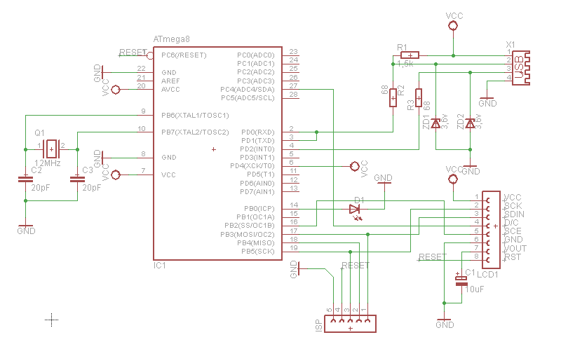
The TiltStick employs a compact design that integrates a two-axis accelerometer, enabling it to detect and measure motion and tilt. The accelerometer chips used in the TiltStick, either the Analog Devices XL203 or the Freescale MMA7261, are crucial for its functionality. The Analog Devices chip operates at a supply voltage of 5V, necessitating the use of zener diodes to step down the voltage on the USB data lines to a compatible 3.6V. This ensures that the device can interface correctly with USB hosts without risking damage to the components.
The Freescale version of the TiltStick is designed with future expansion in mind, as it is prepared to support a third axis of motion sensing. However, the firmware currently does not support this feature. The calibration process is a critical aspect of the TiltStick's operation, allowing users to align the device's output with its physical orientation. The multi-step calibration process, indicated by the LED status, ensures accurate readings by allowing the device to learn its position in space.
In terms of connectivity, the TiltStick is designed to function as a USB joystick, making it compatible with a wide range of USB-equipped devices without requiring additional drivers. This plug-and-play capability enhances user experience by simplifying setup procedures. The internal EEPROM memory allows for the storage of calibration data, ensuring that settings persist across sessions.
The design also includes provisions for GPIO functionality on certain pins, which can be utilized for additional features or modifications in future iterations. The noted design errors, such as the necessity to swap USB data lines, highlight the iterative nature of electronic design, where real-world testing leads to adjustments and improvements.
Overall, the TiltStick represents a versatile tool for motion detection, with potential applications in gaming, robotics, and other fields where orientation sensing is beneficial. Its simple calibration process, combined with its USB compatibility, makes it an accessible option for users looking to integrate motion sensing capabilities into their projects or devices.The TiltStick is a small acceleration sensing device in form of a USB stick. It's using a two axis acceleration sensor to measure acceleration (caused e.g. by motion and tilt). The device is emulating a USB joystick and can thus be used in conjunction with any USB equipped host (e.g. a standard PC or the Nokia N8XX family) without any special drivers. The TiltStick is the successor of the Tilt Dongle for Palm OS. Two versions of the TiltStick have been designed based on different 2D accelerometer chips. The slightly smaller one is based on the Analog Devices XL203 (the XL202 may also be used). The bigger version is based on the Freescale MMA7261. The advantage of the freescale version is that a pin 3D chip exists. The hardware of the TiltStick is prepared to support the third axis. The current design V1.0 contains some design errors. Most important the USB data lines have to be swapped. This can easily be done by cutting the traces directly at the connector and replacing them with thin wires. Press and hold the calibration button (the one close to the USB connector) on the TiltStick for at least three seconds until the green LED turns off.
The yellow calibration LED will then start blinking once a second to indicate that step one of the self calibration is in progress. Hold the TiltStick "flat" and press the calibration button again within 15 seconds. The yellow LED will start flashing twice each second to indicate that this was successful and that the second step of the calibration is to be performed.
Tilt the TiltStick 90 degrees to the right and again press the calibration button within 15 seconds. The LED will start blinking three times each second. Tilt the TiltStick 90 degrees down and once more press the calibration button within 15 seconds. The LED will start blinking four times each second. Fortunately the USB HID drivers are included and joystick devices are detected and included into the input event subsystem. The only part missing is the handling of the actual joystick events and their forwarding to the application that wants to make use of the joystick.
The following section explains how to access the TiltStick by directly interfacing to the linux input event subsystem. The same approach may be used to build a generic software interface to use a standard USB joystick or gamepad with Maemo.
Press the calibration button one last time within 15 seconds to permanently store the new calibration data inside the sticks internal eeprom memory. The yellow LED will stop flashing and the green LED will turn on again. Calibration is done! Furthermore are the ADC6 and ADC7 pins used as GPIO. This doesn't affect the ADI solution as this isn't using those pins, but some changes are needed for the Freescale version.
These aren't documented yet as the current firmware doesn't yet support the freescale chip. Finally the ADI version is missing a connection between PC3 and GND (can easily be fixed directly at the pin) which will allow future firmware versions to differ between the ADI and Freescale boards. The different accelerometers run at different voltages. Thus the ADI version runs at 5V and two zener diodes convert the voltages on the USB data pins to USB compatible 3.6V.
The Freescale chip runs at max. 3.6V. This the supply voltage of the entire unit is reduced by two diodes to approx 3.6V. Thus no further conversion of the voltage on the USB data lines is required. 🔗 External reference
Related Circuits
This design is based on the work of Andrew Bruno, referred to as "bruno-if." The contribution involved providing Postscript files for a Printed Circuit Board. The circuit is relatively old, dating back to the NMEA-0180 and NMEA-0182 standards. It...
The PC parallel port can be easily damaged by wiring mistakes, short circuits, or the circuits connected to it. If the parallel port is integrated into the motherboard, as is the case with most computers, repairs can be expensive....
What can be done with an old phone, a microcontroller, and plenty of time? One possibility is to connect the old phone's LCD screen to a computer's USB port. Connecting an old phone's LCD screen to a computer using a...
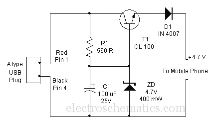
A mobile phone can be charged using the USB outlet of a PC. This simple USB cellphone charger circuit provides a regulated output of 4.7 volts for charging the mobile phone. The USB outlet typically supplies 5 volts DC...
This project involves a mini USB car charger circuit that is simple to construct using only three components. The core of the circuit is the LM78M05 integrated circuit (IC), which is a 5V positive voltage regulator. This IC includes...
This project involves controlling an AVR microcontroller (MCU) using Visual Basic 6. The applications of this circuit are numerous, enabling the creation of various devices that require control from a Personal Computer (PC) or any circuit that collects data...