
Connecting Nokia 3310 LCD to USB using AVR
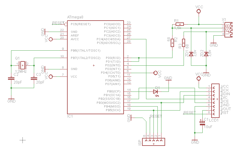
Connecting an old phone's LCD screen to a computer using a microcontroller presents an interesting project that combines elements of hardware interfacing and programming. The process involves several steps, including the disassembly of the phone, identification of the LCD screen connections, and the design of a suitable interface using a microcontroller.
Initially, the old phone must be disassembled to access the LCD screen. This typically involves carefully removing the back cover and disconnecting any cables or connectors that link the screen to the phone's mainboard. It is essential to document the wiring and connections to ensure proper reconnection later.
Once the LCD screen is accessible, the next step is to identify the pinout of the LCD. Most LCD screens utilize a specific communication protocol, such as SPI (Serial Peripheral Interface) or I2C (Inter-Integrated Circuit). Researching the specific model of the LCD screen can provide valuable information on its operational requirements, including voltage levels and data format.
After determining the communication protocol, a microcontroller, such as an Arduino or Raspberry Pi, can be utilized to facilitate the connection between the LCD screen and the computer's USB port. The microcontroller must be programmed to handle the data transmission between the LCD and the computer. This may involve writing code to interpret commands sent from the computer and convert them into signals that the LCD can understand.
The connection to the computer can be established using a USB interface, which may require additional components such as a USB to serial converter if the microcontroller does not have native USB support. Proper power management is also crucial, as the LCD may require specific voltage levels that need to be regulated by the microcontroller.
Once the hardware setup is complete, testing the connection and functionality of the LCD screen is essential. This can involve sending simple commands from the computer to display text or graphics on the LCD. Debugging any issues that arise during this phase is an important part of the project, ensuring that the communication between the computer and the LCD screen is reliable.
Overall, this project not only repurposes an old phone's LCD screen but also provides an opportunity to learn about electronics, programming, and hardware interfacing. The skills gained from such a project can be beneficial for future endeavors in electronics and embedded systems.What do you do with an old phone, a microcontroller and lots of time? You hook the old phone`s LCD screen to the computer USB of course. 🔗 External reference
Related Circuits
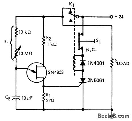
A time delay circuit utilizing a Unijunction Transistor (UJT). The maximum time delay is adjustable via a 10 MΩ potentiometer, allowing the time delay to be configured from less than one second to approximately 2.5 minutes, as referenced by...
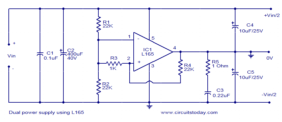
This dual power supply utilizes the L165 power operational amplifier from SGS-Thomson Microelectronics. The L165 IC can deliver up to 3.5A of current, with internal current limiting. It is available in a Pentawatt package, making it well-suited for power...
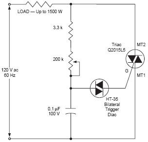
The DIAC, or diode for alternating current, is a trigger diode that conducts current only after its breakdown voltage has been momentarily exceeded. Most DIACs are utilized in applications requiring a switching function in AC circuits. The DIAC is a...
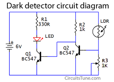
This is a basic dark detector or sensor circuit diagram based on a photoresistor (LDR) and a few components. The dark detector circuit utilizes a photoresistor (LDR) as the primary sensing element. The LDR is a light-dependent resistor that changes...
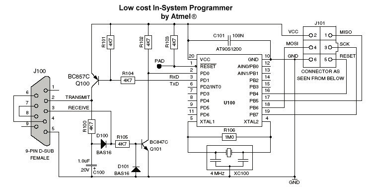
A programmer is available in the "AVR Software and Technical Library - April 2003" CD-ROM and has been published due to its stability and compatibility with AVR Studio 4. It has been tested with the AT90S2313 microcontroller and functioned...
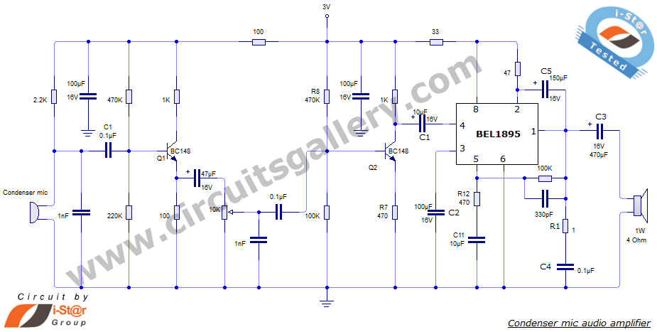
This document presents an audio amplifier circuit suitable for use in walkie-talkies, low-power transmitters, and packet radio receivers. The circuit utilizes a condenser microphone audio amplifier that delivers high-quality audio output of 0.5 watts at 3 volts. The design...