
PC Output Interface

The PC parallel port serves as a convenient interface for controlling external devices, making it particularly useful for hobbyists and experimenters. The integration of the ULN2083 octal transistor array enhances the parallel port's capability by buffering the output current, thereby allowing the control of higher power devices such as relays and motors without risking damage to the PC's internal components. The active low configuration of the outputs necessitates careful consideration in circuit design, ensuring that the external devices are correctly powered and activated in response to the digital signals from the PC.
The flexibility of using a positive voltage supply ranging from +5V to +50V allows for compatibility with a wide variety of external components. This adaptability is crucial in prototyping and testing different circuits, as it enables the user to select the appropriate voltage level based on the requirements of the connected devices. The use of the Parashell software streamlines the process of sending commands to the parallel port, allowing for straightforward control over the output pins. The command structure, utilizing hexadecimal addressing and decimal output commands, is designed to be user-friendly while providing the necessary functionality for effective device management.
In summary, the described circuit provides a robust solution for interfacing a PC with external devices through the parallel port, leveraging the ULN2083 for current amplification and utilizing accessible software for command execution. This combination of hardware and software creates a versatile platform for experimentation and development in electronics.The PC parallel port can be easily damaged by wiring mistakes, short circuits or the circuits you connect to it. If the parallel port is integrated into the motherboard, as is the case with most computers repairs can be expensive.
You can buy inexpensive I/O card which connect to a spare slot on most motherboards, these are ideal for experimentors and easy to replace. Every reasonable care has been taken in producing this information. However, the author can accept no responsibility for any damage arising from mis-use of this information. Please also see this sites general Disclaimer. A versaile output interface that can control external devices direct from your computer. Uses freely available software and works with both windows and Linux. Any PC that has a free parallel printer port available should work with this circuit. The schematic shown above requires little explanation. Any data sent to the printer port is already "latched" and just requires buffering to be able to drive an external ciruit.
In this case I have chosen to use the ULN2083 octal transistor array to buffer the output current from the parallel port. The IC pinout for the ULN2083 is shown below. The pararell printer port on your PC is a 25 way D type connector. Its pinout is shown below. Pins 2 to 10 are the data output lines D0 to D7. Pins 18 through 25 are ground pins, the other pins are not used and left unconnected. The output current is amplified by the ULN2083 and each output pin can supply a load of up to 50mA. The outputs are active low, meaning that a high logic input gives a low logic output. To get around this the output load is routed to a positive voltage, so that any high input will now produce a high output.
The positive supply can be any value from +5 to 50Vdc, I used 12V relays and so used a 12V supply in my design. All that is needed is a way to send data to the printer port and control the output circuits. The program I have chosen to work with this interface is Parashell, created by Brett Carol and hosted on Sourceforge.
The software is free to use and as of Version 2. 1 will work both on Windows and Linux. A quick install guide follows for both operating systems. Unzip the file parahell-2. 1. zip With Windows Xp simply clicking on the file will expand its contents. Double click on the bin, hen the windows folder, and drag the file parashell to your desktop. Open a command prompt and proceed as in Testing. In this example I am using Suse 10. 1 First download Parashell to your home directory, click here for the link. At the time of writing the current version is parashell-2. 1. zip Download parashell-2. 1. zip to your home directory, then open a terminal and unzip the package (as the package contains binaries for both windows and linux it is compressed in zip format instead of the usual. tar. gz and. tar. bz2 linux formats. ) Connect the PC output interface to the printer port on your computer. If your computer only has one parallel port then its address will be 378 (in hex). This is represented by 0x in the parashells syntax. Once the software is installed open a command prompt (windows) or terminal (linux) and type: Parashell output commands are in decimal, the outputs D0 through to D7 are in binary.
Hence if you want to control individual pins you just look up their value in the binary to decimal conversion table below. For example, if you had a circuit connected to pin D5 then you would use parashell 0x378 32 to enable D5, and 0 to disable it.
If you had circuits connected to D2 and D3 and wanted to make them active at the same time, then add the decimal values together, i. e. parashell 0x378 12 would simultaneously activate D2 and D3. All outputs remain latched until a zero is sent to the desired output pin. If you had multiple circuits, then sending the command parashell 0x378 0 would turn all outputs off. This may be undesirable and if for example you had circuits conne 🔗 External reference
Related Circuits
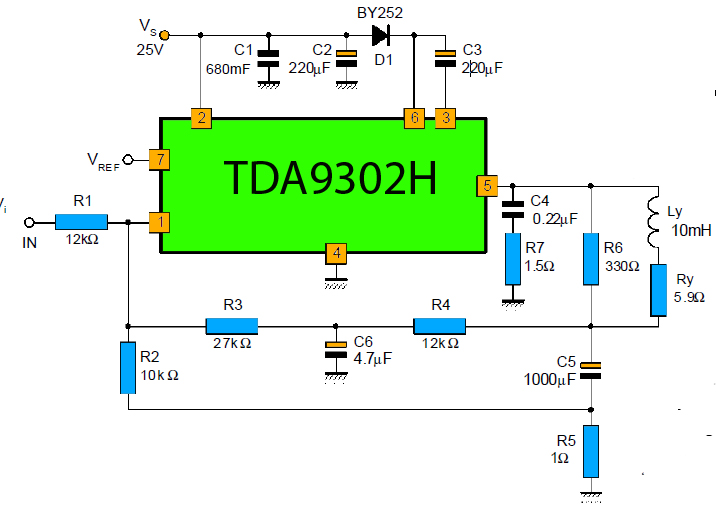
The TDA9302H is a monolithic integrated circuit housed in a HEPTAWATTTM package. It functions as a high-efficiency power amplifier designed for direct drive vertical deflection coils in television yokes. This component is suitable for use in both color and...
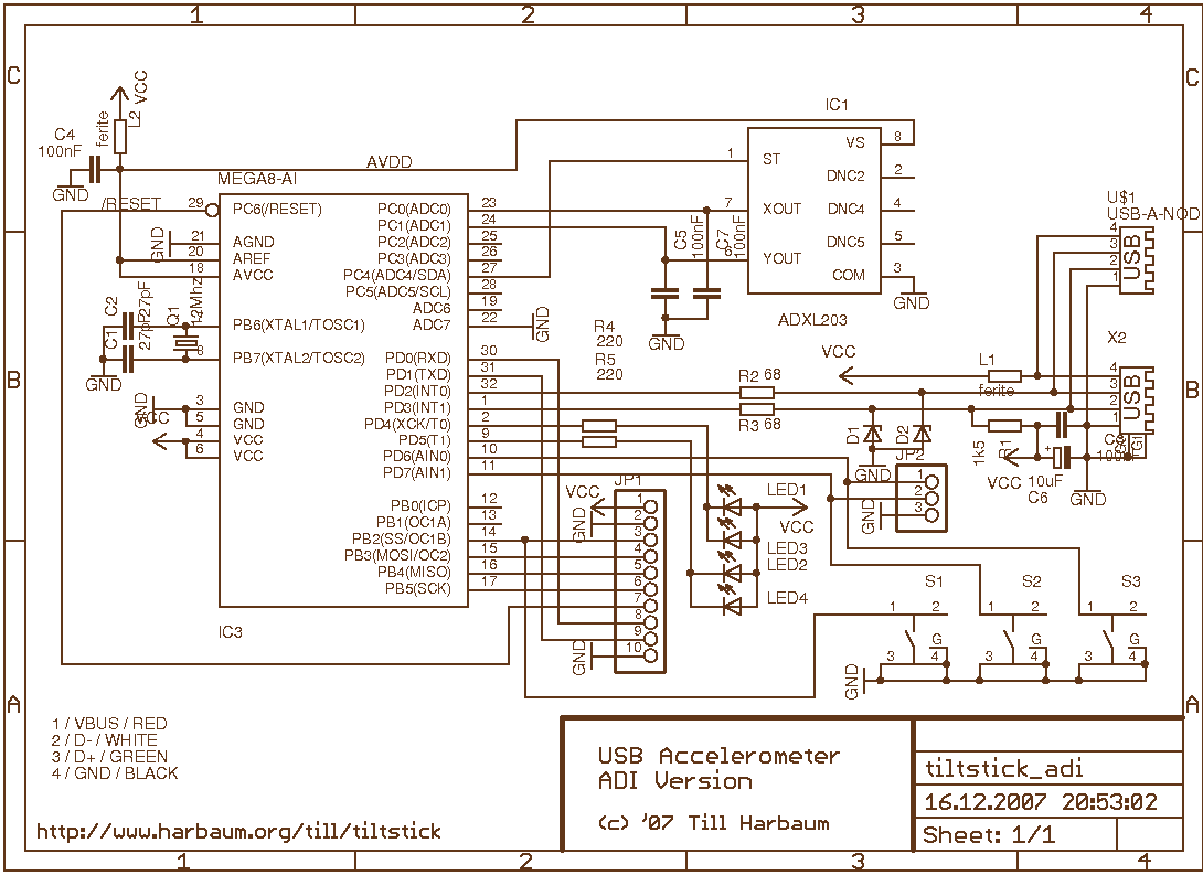
The TiltStick is a small acceleration sensing device in the form of a USB stick. It's using a two-axis acceleration sensor to measure acceleration (caused e.g. by motion and tilt). The device is emulating a USB joystick and can...
This project involves controlling an AVR microcontroller (MCU) using Visual Basic 6. The applications of this circuit are numerous, enabling the creation of various devices that require control from a Personal Computer (PC) or any circuit that collects data...
The circuit features a serial coded modulated control signal that amplifies and transmits high-voltage isolation. It utilizes a 556 timer-based circuit along with resistors R1, R2, capacitors C1, and R3, R4, C2 to form two astable multivibrators. The circuit...
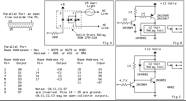
Below are three examples of controlling a relay from the PC's parallel printer port (LPT1 or LPT2). Figure A shows a solid-state relay controlled by one of the parallel port data lines (D0-D7) using a 300-ohm resistor and a...
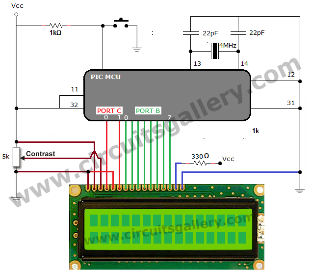
The process of interfacing an LCD (Liquid Crystal Display) module with a PIC microcontroller involves understanding the nature of LCDs as passive components that modify light rather than generate it. LCDs are specifically designed for use with microcontrollers and...