
Accelerometer Circuit
The accelerometer operates by detecting changes in motion and orientation, which are translated into electrical signals. The Memsic 2125, as a dual-axis accelerometer, utilizes MEMS (Micro-Electro-Mechanical Systems) technology to achieve its measurements. It has two output pins, which provide voltage levels corresponding to the tilt angles in the X and Y axes. The Arduino microcontroller processes these voltage signals, converting them into digital values that can be interpreted and displayed.
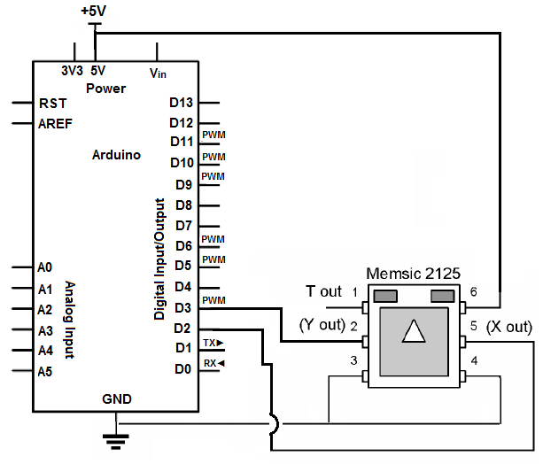
To set up the circuit, the accelerometer is connected to the Arduino as follows: the VCC pin of the accelerometer is connected to the +5V power supply, ensuring the device is adequately powered. The GND pins are connected to the ground of the Arduino, establishing a common reference point for voltage levels. The Y OUT pin (Pin 2) connects to digital pin D3, while the X OUT pin (Pin 5) connects to digital pin D2. These connections allow the Arduino to read the tilt data as digital signals.
The programming aspect involves writing a sketch in the Arduino IDE that continuously reads the values from the accelerometer. The values are processed to calculate the tilt in milli-g's, which can be displayed on a serial monitor or an LCD screen. The code can also include conditional statements that monitor the tilt values and activate an output, such as a siren, when the tilt exceeds a predefined threshold. This functionality is critical for applications where maintaining a specific orientation is vital, such as in mobile devices, robotics, or any system where stability is paramount.
In summary, the integration of an accelerometer with an Arduino microcontroller enables the measurement of tilts and movements, facilitating various applications in alarm systems and device stability monitoring. The ability to program responses based on tilt measurements enhances the versatility and functionality of electronic systems.As you are probably familiar, an accelerometer is a device that can measure dynamic acceleration (vibrations) and static acceleration (gravity). Being that it measures this, it can measure tilts, rotations, and movements/lack-of-movements for alarm system sensing.
Basically, it can measure if it`s being tilted, rotated, or moved around. Being that an accelerometer measures tilts, it needs a microcontroller to be able to read these tilts and record how much it is tilted. The microcontroller we will connect to the accelerometer is an arduino microcontroller. Tilts and imbalances on accelerometers are measured in unit millig`s. A millig (mg) is a 1/1000th of a g. Being that the g-force is equal to 9. 81m/s2, a millig is equal to 1/1000th of this value. The memsic 2125 is a dual- or two-axis accelerometer. It can measure tilts in the 2 directions, the X-direction and the Y-direction. This means that if we shift it left and right, this is the X-direction. If we shift it forward or backward, this is teh Y-direction. The memsic is able to record these movements and then the arduino can sense and output to us the data.
To connect the accelerometer, we give it +5VDC of power. Accelerometers need power in order to operate. We connect both GND pins to GND. These are Pins 3 and 4. Then we connect Pin 2, Y OUT, to D3 of the arduino. We connect Pin 5, X OUT, to D2 of the arduino. Terminals D3 and D2 of the arduino are digital input pins, which receive the digital readings that the accelerometer gives out, showing its X and Y axis tilt readings. Now that we have connected the circuit, we now need to create a program which calculates the millig readings and can display to us on the computer so that we can know all the readings that go on as the accelerometer is tilted.
Once we put this code in the arduino processing software and run the code, we will get out all the readings of the X and Y axes. If we tilt the accelerometer in the X direction, the milli-g`s reading will be much greater of the X axis.
If we tilt the accelerometer in the Y direction, the milli-g`s reading of the Y axis will be much greater. Accelerometers are important because they measure this tilt. If we have an electronic device that can only sustain a certain amount of tilt, we can w write code so that if it tilts more than a certain amount of milli-g`s, an event can occur.
For example, if a user tilts an electronic device more than 900 milli-g`s, a siren will loud. We can connect a siren to a digital output pin of the arduino. We can then write code so that if there is a tilt greater than 900 milli-g`s, the siren will be turned on. So this is the tremendous application that accelerometers have. They measure tilt so that an event can be triggered if a device gets too much off balance. 🔗 External reference
Related Circuits

This is a circuit design for a doorbell that produces a bird-like sound. The circuit is controlled by an NPN transistor. The operation of the circuit begins when P1 is set to an experimental value, starting with approximately 220...
This circuit design has not been tested by staff. The design, as submitted by the designer, is believed to be correct; however, there is no guarantee of its accuracy. The content provided may be inaccurate, inappropriate, or misguided. There...
All of the components in this list are generally available through RadioShack for less than $20. It is highly recommended to use a breadboard for assembly, as mistakes are common for first-time builders, and soldering can complicate troubleshooting. This...
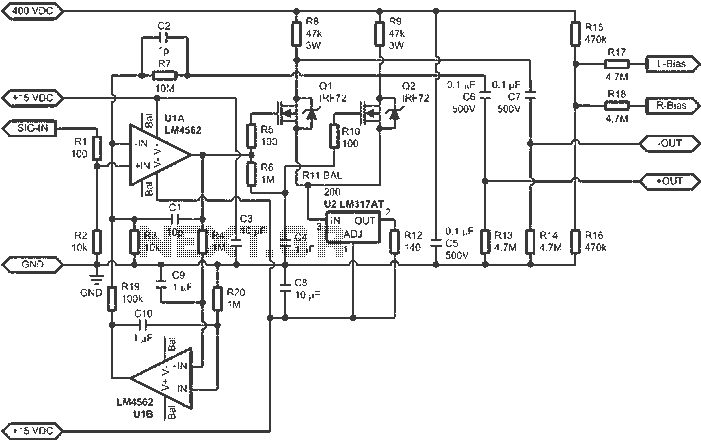
When connected to popular Stax Class 1 electrostatic headphones, the design illustrated in the figures may operate across the full audio bandwidth with a transmission voltage close to 200 Vp-p. Although the resistor divider can be modified to provide...
Here is a circuit diagram for adjusting the brightness of a light bulb. The second battery is utilized to power the circuit. This circuit can be used to modify the brightness of images during close-up photography with a digital...
A functional circuit utilizing an operational amplifier (op-amp); however, the instructor indicated that op-amps can be challenging to work with and provided transistors as an alternative. Operational amplifiers (op-amps) are versatile components commonly used in various electronic circuits for...
Warning: include(partials/cookie-banner.php): Failed to open stream: Permission denied in /var/www/html/nextgr/view-circuit.php on line 713
Warning: include(): Failed opening 'partials/cookie-banner.php' for inclusion (include_path='.:/usr/share/php') in /var/www/html/nextgr/view-circuit.php on line 713