
switching power supply schematic

Switching power supplies are crucial components in modern electronic devices, providing efficient voltage regulation and power conversion. The schematic diagram of a switching power supply typically includes several key components: an input filter, a power switch (usually a MOSFET or IGBT), a transformer, a rectifier, an output filter, and control circuitry.
The input filter is designed to reduce electromagnetic interference (EMI) and protect the power supply from voltage spikes. It typically consists of capacitors and inductors arranged to form a low-pass filter. The power switch operates by rapidly turning on and off, allowing energy to be transferred to the transformer during the 'on' state and preventing energy flow during the 'off' state.
The transformer in a switching power supply serves to step up or step down the voltage while isolating the input from the output. It operates at high frequencies, which allows for smaller and lighter components compared to linear power supplies. The output side usually features a rectifier, which converts the AC output of the transformer back into DC, and an output filter that smooths the voltage to ensure a stable output.
Control circuitry is essential for regulating the output voltage and current. It typically uses feedback mechanisms to compare the output voltage with a reference voltage and adjust the duty cycle of the power switch accordingly. This feedback loop ensures that the output remains stable under varying load conditions.
Overall, the design and implementation of switching power supply schematic diagrams require a deep understanding of electronics, including circuit theory, component specifications, and electromagnetic compatibility considerations.Greeting, This post summarize the work of switching power supply schematic diagram experts who are completely familiar with all the aspects of.. 🔗 External reference
Related Circuits
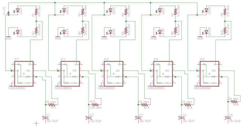
Build a circuit that will flash five pairs of LEDs at variable rates. To achieve this, a circuit utilizing five NE555 timers has been designed. Trim pots will be used to control the variable flash rate. Assistance is needed...
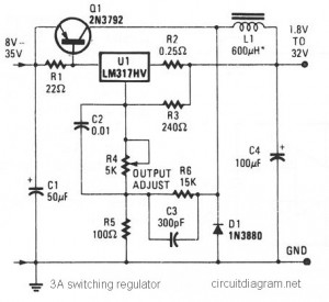
The circuit diagram presented is a simple and cost-effective switching voltage regulator capable of delivering an adjustable output voltage range from 1.8V to 32V with a maximum static current of 3A. This regulator utilizes the adjustable LM317HV IC along...
The circuit is designed to create a power amplifier that utilizes E80CC and EL34 vacuum tubes to achieve optimal performance, providing an output of 35 Watts. The power amplifier circuit employs E80CC and EL34 vacuum tubes, which are known for...
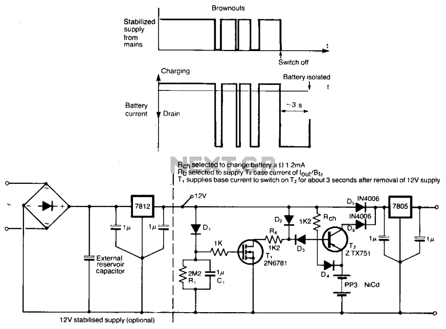
This circuit protects microprocessor systems from brownouts without the cost of an uninterruptible power supply. It is designed around a small 9-V nickel cadmium battery, which continues to provide a constant 5-V output during brownouts lasting up to a...
The schematic diagram below illustrates a simple and cost-effective 12-volt DC 50W off-line SMPS (switched-mode power supply) circuit. It is suitable for DIY home projects or for learning about the operation of flyback converters. This power supply unit (PSU)...
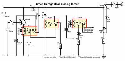
Timer garage door circuit schematic diagram, printed circuit board. The timer garage door circuit is designed to automate the opening and closing of a garage door based on a predetermined time interval. The schematic diagram illustrates the layout and connections...