
Voltage Converter 3V to 5V using MAX660
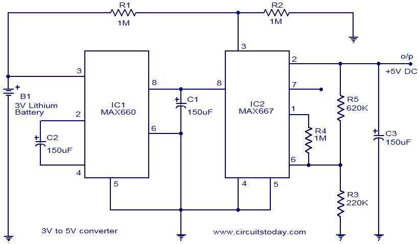
The voltage converter circuit utilizes the MAX660 and MAX667 integrated circuits to step up a 3-volt input to a 5-volt output. The MAX660 is a voltage converter that efficiently boosts lower voltages to higher levels, while the MAX667 acts as a voltage regulator to ensure the output remains stable at 5 volts.
The circuit typically consists of the following components:
1. **Input Capacitor (C1)**: This capacitor is connected to the input voltage (3V) to smooth out any fluctuations and provide stable power to the MAX660. A value of around 10 µF is commonly used for this purpose.
2. **Inductor (L1)**: The inductor is a crucial component in the voltage boosting process. It stores energy when current flows through it and releases it to the output when the circuit switches. The inductor value should be selected based on the desired output current and the switching frequency of the MAX660.
3. **Diode (D1)**: A Schottky diode is typically used in this configuration to prevent backflow of current and to ensure that the energy stored in the inductor is directed towards the output. This diode should have a low forward voltage drop to maintain efficiency.
4. **Output Capacitor (C2)**: This capacitor stabilizes the output voltage and reduces ripple. A value of around 10 µF to 22 µF is recommended for effective filtering.
5. **MAX667 Voltage Regulator**: The MAX667 is connected to the output of the MAX660 to regulate the output voltage at a precise 5 volts. It provides excellent line and load regulation, ensuring that the output remains stable under varying conditions.
6. **Feedback Resistor Network (R1 and R2)**: These resistors set the output voltage level for the MAX667. The resistor values must be chosen based on the desired output voltage and the feedback configuration of the regulator.
The entire circuit should be designed on a printed circuit board (PCB) to minimize noise and interference, ensuring reliable operation. Proper layout techniques, including keeping high-frequency paths short and using ground planes, will enhance the performance of the voltage converter circuit.
In summary, this voltage converter circuit effectively steps up a 3V input to a stable 5V output using the MAX660 and MAX667 ICs, making it suitable for applications requiring a higher voltage from a lower voltage source.Voltage Converter Circuit diagram for 3 volts to 5 volts (3v to 5v) using IC (CMOS Monolithic) MAX660 and MAX667-a positive voltage regulator 🔗 External reference
Related Circuits
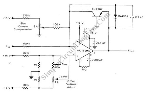
This low-cost logarithmic converter is constructed using an operational amplifier (op-amp) and a transistor. The circuit utilizes a Motorola MC1539G op-amp connected to a PNP transistor. The logarithmic converter circuit is designed to convert linear input signals into logarithmic output...
In the precision circuit, an operational amplifier provides a buffered output and also functions as a 2-pole filter. The ripple will be less than 5 mV peak for all frequencies above 1 kHz, and the response time will be...
As Ron suggests, controlling the output voltage from a regulator can be made variable in three ways. Using a fixed reference zener diode to increase the output by the value of the zener. A variable resistor for variable output,...
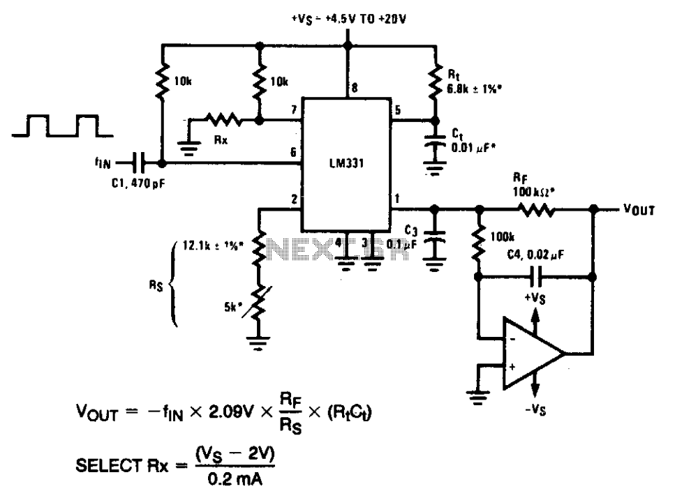
The AD654 is a monolithic voltage-to-frequency (V/F) converter that comprises an input amplifier, a precision oscillator system, and a high-current output stage. A single resistor-capacitor (RC) network is all that is needed to configure any full-scale (FS) frequency up...

Author Mazi Hosseini describes a simple, low-cost voltage-controlled current source using two operational amplifiers that provides a good range of current and maximum load. The circuit described by Mazi Hosseini utilizes two operational amplifiers (op-amps) to create a voltage-controlled current...
The UTC7642 is designed for use in low voltage portable radio cassette systems and other wireless AM systems. It is packaged in a TO-92 casing. The manufacturer is LianShun Electronics Co., Ltd. The UTC7642 is a low-voltage operational amplifier...