
voltage How to amplify 3.3 volts to 8-9v
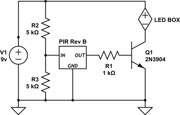
To design an effective circuit based on the requirements outlined, a transistor can be utilized as a switch to control the LED activation. The Parallax PIR sensor, which outputs a 3.3V signal, will be connected to the base of the transistor. A typical NPN transistor, such as the 2N3904, can be employed for this purpose.
The collector of the transistor will be connected to the LED box, while the emitter will be connected to ground. A pull-down resistor (approximately 10kΩ) should be placed between the base of the transistor and ground to ensure that the transistor remains off when the PIR output is low. To protect the transistor from excessive current, a resistor (typically 1kΩ) should be placed in series with the base.
The LED box, operating at 8-9V and requiring 8mA, will be powered by a 9V battery. The positive terminal of the battery will connect to the anode of the LED box, while the cathode will connect to the collector of the transistor. When the PIR sensor is triggered, it will output a 3.3V signal to the base of the transistor, allowing current to flow from the collector to the emitter, thus illuminating the LED box.
It is crucial to ensure that the transistor can handle the current requirements of the LED box. The specifications of the chosen transistor should be reviewed to confirm it can adequately support the load. Additionally, the PIR sensor's datasheet should be consulted to understand its output current capabilities, ensuring that it can effectively drive the base of the transistor.
This circuit configuration allows for the LEDs to be activated for the duration that the PIR sensor is triggered, providing a practical solution to the initial problem while ensuring that the components are correctly matched to their operational requirements.Turn on a "black box" of leds (that operates at 8-9v) when my motion sensor is activated. The problem I`ve got is that the output of my PIR is only 3. 3 volts. Here is my crappy schematic. There are a few things that need to be fixed. First, A resistor is not a good way to reduce voltage. Second, a model number for the PIR sensor, would be useful. As would the current requirements for the LED box. How are the leds normally connected to power, a dc wallwart/adaptor Most PIR sensors outputs are only on for a very small amount of time per trigger, with a lockout period, so the leds might only be on for a very short time. A generic answer would be using a transistor as a switch, but you need to know the PIR output current and the LED box current for a proper answer.
Passerby Apr 16 `13 at 0:53 Im using the Parallax PIR : parallax. com/tabid/768/productid/83/default. aspx The Led Box current requierement is 8mA (it is a "solder yourself" blinking leds kit) and I just happend to want to turn it on when the PIR sensor is activated. Power will be coming from a 9v battery. Rhyuk Apr 16 `13 at 1:08 🔗 External reference
Related Circuits
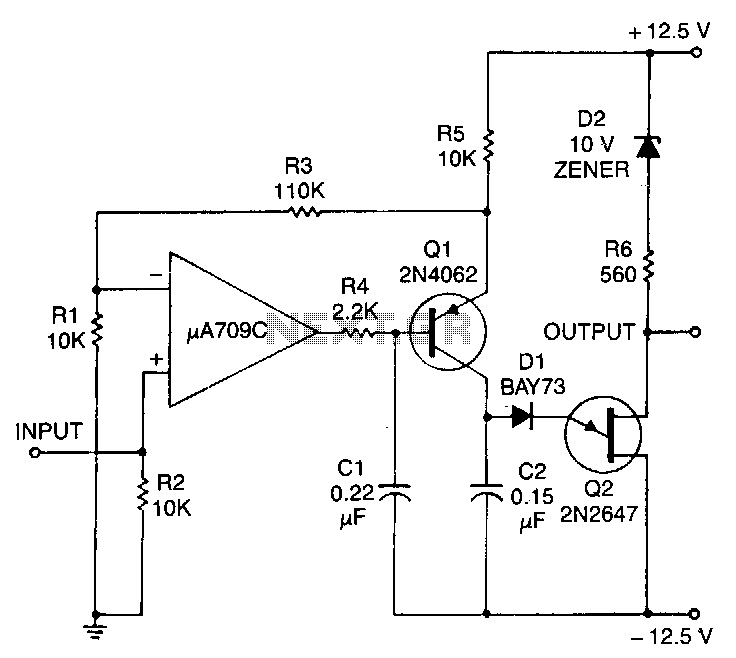
This circuit consists of a UJT oscillator where the timing charge capacitor C2 is linearly dependent on the input signal voltage. The charging current is determined by the voltage across resistor R5, which is precisely controlled by the amplifier....
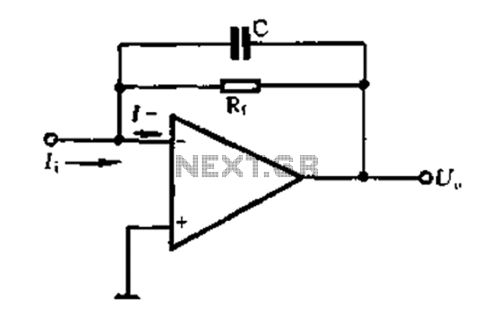
A current-voltage conversion circuit. A current-voltage conversion circuit is designed to transform an input current signal into a corresponding voltage signal. This type of circuit is fundamental in various applications, including sensor interfacing, signal conditioning, and analog-to-digital conversion processes. Typically,...
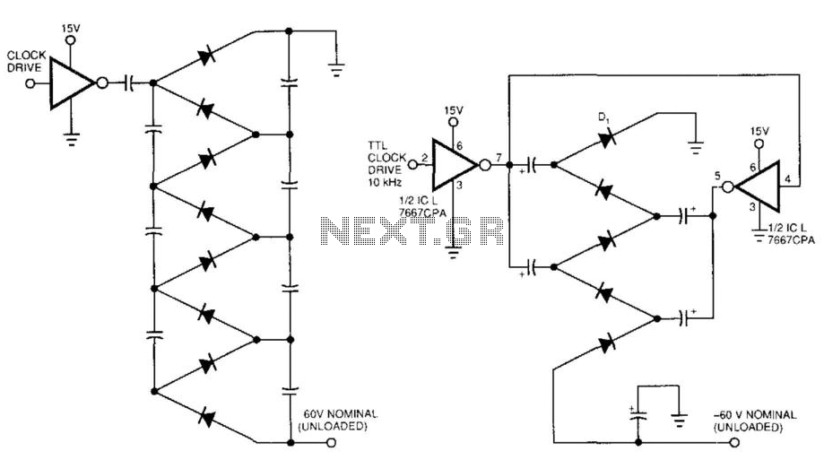
Figure 99-1(a)'s circuit exhibits a high output impedance due to the small effective capacitance of the series-connected capacitors, resulting in considerable voltage loss from the diode drops. This circuit requires two diodes and two capacitors to generate a DC...
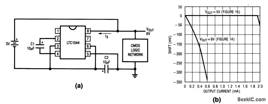
This circuit doubles the available battery voltage using an LTC1044 switched-capacitor voltage converter. It is designed to power low-power 74-CMOS (3 to 15 V) equipment for extended periods from two small 1.5 V cells. The efficiency exceeds 90% for...
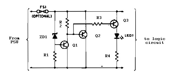
Logic overvoltage protection power supply. Refer to the designated page for an explanation of the power supply circuit diagram mentioned above. The logic overvoltage protection power supply is designed to safeguard sensitive electronic components from voltage spikes that could potentially...
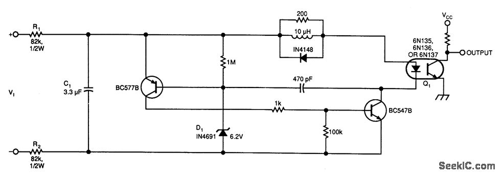
This circuit below illustrates a simple voltage-controlled oscillator (VCO) connected to instrumentation via an optoisolator. The voltage-controlled oscillator (VCO) circuit operates by generating a periodic waveform whose frequency is determined by an input control voltage. The primary components of this...