
Voltage, Ampere Digital meter
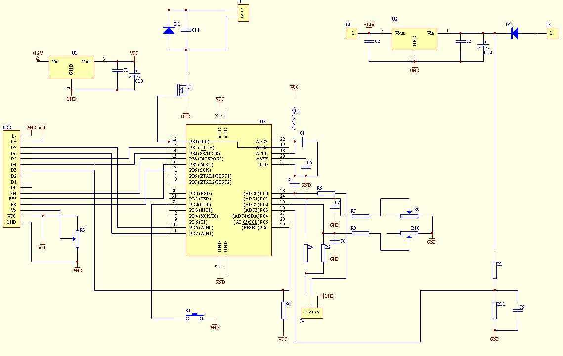
This multimeter circuit is engineered for precise measurement of voltage and current in a power supply unit (PSU). The design incorporates a current sense shunt resistor, strategically placed in series with the load on the negative voltage rail, allowing for accurate current readings. The multimeter operates on a single supply voltage derived from the main PSU, ensuring simplicity and efficiency in its power requirements.
An integral feature of this multimeter is its ability to control an electric fan, which is essential for cooling the main heatsink. The activation of the fan is determined by a power threshold that can be conveniently adjusted using a One Touch Button Setup. This feature enhances the functionality of the multimeter, making it suitable for applications where thermal management is critical.
The core of the multimeter's functionality is managed by an ATMEL ATmega8 microcontroller, which oversees all operations and data processing. The voltage measurement range is set between 0-30V, with a resolution of 10mV, providing precise voltage readings. Current measurement is also facilitated with a resolution of 10mA, which is contingent upon the value of the current sense resistor employed in the circuit.
The multimeter is designed to operate on a single, non-isolated voltage supply and features a one-sided printed circuit board (PCB) layout, contributing to a compact construction that allows it to function effectively as a panel meter. Additionally, the multimeter is compatible with standard LCDs based on the HD44780 controller, which simplifies the display interface.
For optimal performance, it is necessary to ensure that the microcontroller is properly programmed and recognized by the programming interface. The recommended settings include operating the microcontroller at its internal RC clock frequency of 1MHz and enabling the Brown-out Detector (BODEN fuse) with a reset threshold voltage of 4V.
When integrating the LCD module with the multimeter PCB, it is crucial to solder the appropriate pads to provide a ground connection for the LCD's RW signal. The use of a detachable connector is advised to facilitate potential future upgrades or software modifications.
Safety precautions are paramount when working with this circuit, as it does not operate off mains power but is connected to a PSU that may present high voltages. Caution should be exercised to prevent exposure to voltages exceeding 50V, which are potentially dangerous. It is essential to follow safety guidelines meticulously, such as avoiding work when fatigued, ensuring proper insulation of mains leads, and utilizing appropriate personal protective equipment during testing. These measures are critical to safeguarding both the user and others in the vicinity.This multimeter was designed to measure output voltage and current in a PSU, where the current sense shunt resistor is connected in series with load at the negative voltage rail. It needs only one supply voltage that can be acquired from main PSU. An additional function of the multimeter is that it can control (switch on and off) an electric fan used to cool the main heatsink.
The power threshold at which the fan switches on can be adjusted using One Touch Button Setup. single uC ATMEL ATmega8 used to handle all the multimeter functions. voltage range 0-30V. voltage measure resolution 10mV. current measure resolution 10mA (depended on current sense resistor value). single, non isolated voltage supply. one side PCB. compact construction allowed to use the multimeter as panel meter. compatibility with standard LCDs based on HD44780 controller. After connecting ?C to prog, you should check, if ?C is "visible" for prog. When everything is fine, you can upload code to ?C. The code is available >here< .It is assumed that ?C is new and works with its internal RC clock at 1MHz. If not, set appropriate fuse bits to achieve above mentioned conditions. In addition Brown-out detector should be turned on by enabling BODEN fuse. Recommended Brown-out Reset Threshold Voltage is 4V. The next thing to do is to cross LCD soldering pads number 1 and 5. That's necessary to provide ground for LCD RW signal. After all, connect LCD module with the multimeter PCB. It is recommended to use a detachable connector for further expandability e.g. software upgrading. CAUTION This circuit itself doesn't work off the mains and there are not 220 VAC present, but PSU does.
Voltages above 50 V are DANGEROUS and could even be LETHAL. In order to avoid accidents that could be fatal to you or members of your family please observe the following rules: DO NOT work if you are tired or in a hurry, double check every thing before connecting your circuit to the mains and be ready to disconnect it if something looks wrong. DO NOT touch any part of the circuit when it is under power. DO NOT leave mains leads exposed. All mains leads should be well insulated. DO NOT change the fuses with others of higher rating or replace them with wire or aluminium foil. DO NOT work with wet hands. If you are wearing a chain, necklace or anything that may be hanging and touch an exposed part of the circuit BE CAREFUL.
ALWAYS use a proper mains lead with the correct plug and earth your circuit properly. If the case of your project is made of metal make sure that it is properly earthen. If it is possible use a mains transformer with a 1:1 ratio to isolate your circuit from the mains. When you are testing a circuit that works off the mains wear shoes with rubber soles, stand on dry non conductive floor and keep one hand in your pocket or behind your back. If you take all the above precautions you are reducing the risks you are taking to a minimum and this way you are protecting yourself and those around you.
A carefully built and well insulated device does not constitute any danger for its user. 🔗 External reference
Related Circuits
A circuit of measurement of level based on a typical application of National. The circuit round the IC1 makes input adaptation and amplification with the trimmer TR1 [GAIN]. The circuit round the IC2 makes half-wave rectification of acoustic signal....
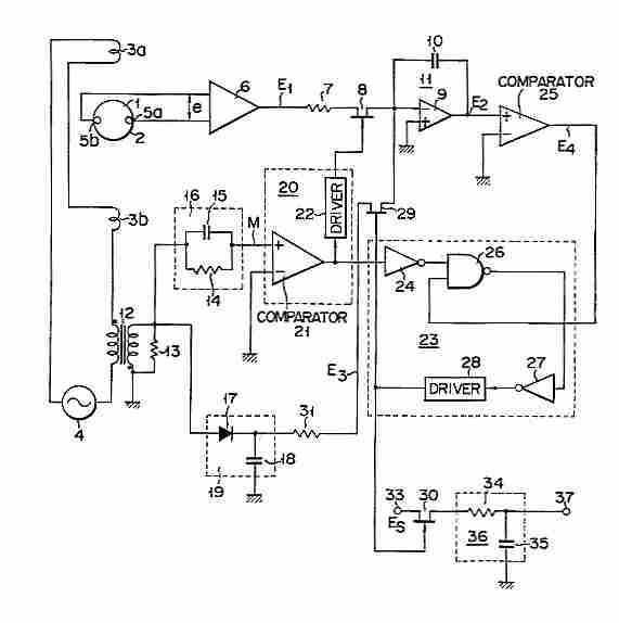
Electromagnetic flow meter: How to measure fluid flow using a magnetic field. An electromagnetic flow meter is a device used to measure the flow rate of conductive fluids by utilizing Faraday's law of electromagnetic induction. This principle states that when...
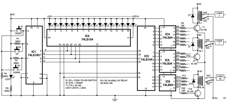
This circuit is capable of controlling one out of 16 devices using two push-to-on switches. An up/down counter functions as the master controller for the system, and visual feedback is provided through LEDs. The circuit employs IC1 (74LS193), which...
When an antenna is attached, or even if not, in the presence of a strong RF field, the field strength meter has a moving coil meter to indicate relative field strength. The box holds a Schottky diode detector, a...
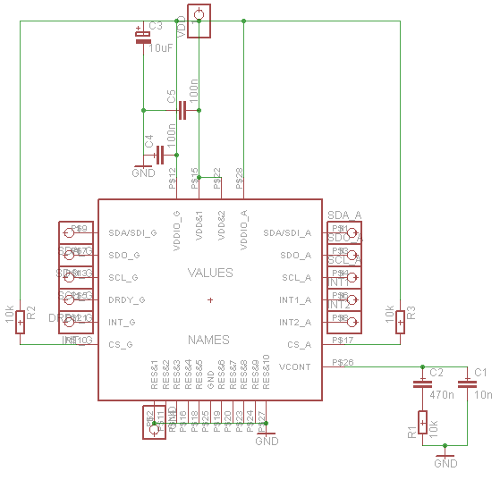
Establish communication between the microcontroller unit (MCU) and the accelerometer using either I2C or SPI protocols. It has been noted that shorting the phase-locked loop (PLL) filter input in the device does not affect the readings from the gyroscope...
A digital voltmeter, or any voltmeter with millivolt resolution and high input impedance, can be utilized as a temperature-to-voltage adapter. The described temperature-to-voltage adapter is designed to convert temperature readings into corresponding voltage outputs, suitable for interfacing with digital voltmeters....
Warning: include(partials/cookie-banner.php): Failed to open stream: Permission denied in /var/www/html/nextgr/view-circuit.php on line 713
Warning: include(): Failed opening 'partials/cookie-banner.php' for inclusion (include_path='.:/usr/share/php') in /var/www/html/nextgr/view-circuit.php on line 713