
DEMODULATOR circuit
The amplifier circuit operates by utilizing a biasing technique that places the transistor Q5 at the cutoff point, allowing it to function effectively as a grid-leak detector. The design focuses on maintaining a delicate balance between the chroma signal and the reference subcarrier. The demodulator's operation hinges on the phase relationship between these signals, ensuring that only relevant portions of the chroma signal are allowed to pass through, while unwanted signals are blocked. The low-pass filter formed by capacitor C32 and resistor R22 is crucial for eliminating high-frequency noise that could interfere with the visual output.
The saturation control mechanism is an important aspect of this design, as it directly influences the visual quality of the output. By adjusting the gain, the user can manipulate the color intensity, which is essential for achieving the desired visual fidelity. The relocation of the saturation control to a downstream position enhances the overall performance of the demodulator, allowing for more consistent operation without compromising frequency response.
The inclusion of the emitter bypass capacitor C1B serves to enhance high-frequency gain, but it also introduces a trade-off with low-frequency performance. The design considerations regarding this capacitor reflect an understanding of the complex interplay between various frequency components in the signal. The ability to reproduce low frequencies accurately is vital for maintaining the integrity of the visual output, especially for large details in the image.
Future enhancements, such as the potential addition of a DC restorer or clamp circuit, could further refine the performance of this amplifier circuit, addressing any issues related to background stability and overall signal integrity. The careful design and component selection demonstrate a thorough understanding of the principles involved in signal processing and amplification within this context.amplifier, with bias at cutoff. Q5 acts much like a grid-leak detector. Without the subcarrier input, the demodulator cuts off and prevents signals from passing. Of course, the chroma signal must be at a low level. Otherwise, chroma might gate the demodulator on. Positive excursions of the reference subcarrier are strong enough to gate the demodul ator on. These positive excursions cause Q5 to sample the chroma signal at the reference subcarrier frequency. Whenever the reference subcarrier swings positive, it gates the demodulator on. Whenever the reference subcarrier swings negative, it gates the demodulator off. When the demodulator is off, no signal passes through it. In the demodulator, the subcarrier and chroma mix. The output is only positive subcarrier excursions that coincide with the chroma signal phase. Nothing else passes. Rectification. Only positive chroma excursions survive the trip. That is, the demodulator rectifies the chroma and the reference. During rectification, the demodulator eliminates the lower chroma sideband. A typical AM detector rectifies in the same way. Because the high-frequency subcarrier remains in the output, we need to filter out the subcarrier remnant.
Otherwise, it might appear on the TV screen. The low-pass circuit. Notice capacitor C32 in the transistor Q5 collector circuit. This capacitor and collector resistor R22 form a low-pass filter. The filter attenuates the 3. 58 MHz signal. Attenuation keeps the burst and regenerated subcarriers off the picture tube. Unlike the original Col-R-Tel filter, this filter requires no peaking. After filtration, the demodulator`s output bandpass covers the span from zero to 500 kHz. Saturation Potentiometer VR2 controls how much color that demodulator Q5 passes to succeeding stages. By increasing and decreasing gain, you can change color intensity. An intense or saturated color is pure, and contains little or no black or white. A dark or whitish color has low saturation. In the original, 1955 Col-R-Tel, the control also affects signal equalization. For our purposes, equalization is the amount of low vs. high frequencies. Changes to Saturation Control VR2. In the original, tube version of Col-R-Tel, the saturation control was in the demodulator plate circuit.
To make the saturation control less likely to affect frequency response, I`ve moved the control. Control VR1 now resides downstream from the output coupling capacitor. The new position allows the demodulator to operate at a constant gain and with predictable equalization. By using a high-resistance pot for VR1, I reduce the stage`s current drain. Emitter bypass capacitor C1B might not be necessary. The original Col-R-Tel circuit included this capacitor, so I followed suit. This capacitor increases gain, particularly at high frequencies. The idea is to compensate for the internal capacitance of transistor Q5. This internal capacitance tends to roll off the high frequencies, especially those above about 100 kHz.
Q5`s internal capacitance and maximum gain limit the bypass capacitor`s ability to restore high frequencies. Low frequencies. Because of capacitor C1B, the low frequencies don`t receive nearly as much gain from transistor Q5. The drawback here is that video tends to concentrate near the carrier. The near-carrier frequencies are the lowest ones. These low frequencies tend to be large details, such as outlines and colored backgrounds. Without capacitor C1B, reproduction of low frequencies would be flatter. Making C1B larger would also allow better reproduction of low frequencies. This circuit should reproduce frequencies down to at least 60 Hz. Otherwise, backgrounds might appear insubstantial or snowy. A DC restorer or clamp circuit could rejuvenate such insubstantial backgrounds. The Col-R-Tel circuit doesn`t include such a circuit. I might add one later. Hassle reduction. How about saving some time and money Because both the subca 🔗 External reference
Related Circuits
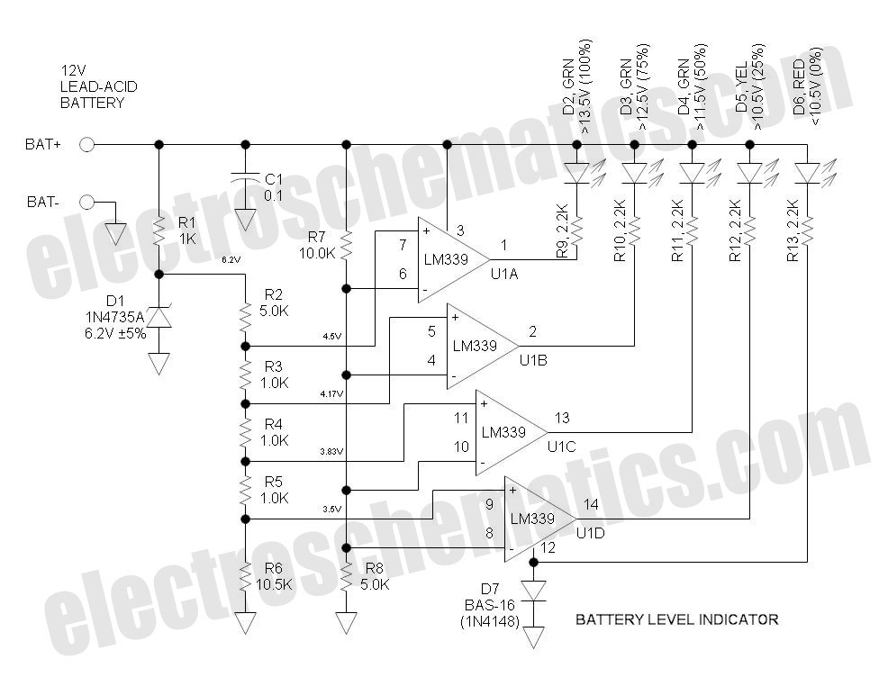
This battery level indicator features five LEDs that illuminate progressively as the voltage increases: Red indicates power connection (0%), Yellow signifies voltage greater than 10.5V (25%). The battery level indicator circuit utilizes a series of five light-emitting diodes (LEDs) to...
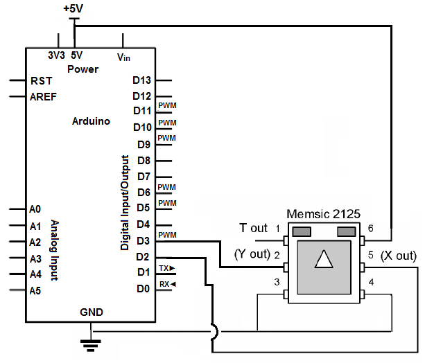
An accelerometer is a device that measures both dynamic acceleration (vibrations) and static acceleration (gravity). It can detect tilts, rotations, and movements or lack thereof, making it useful for alarm system sensing. The accelerometer can determine if it is...
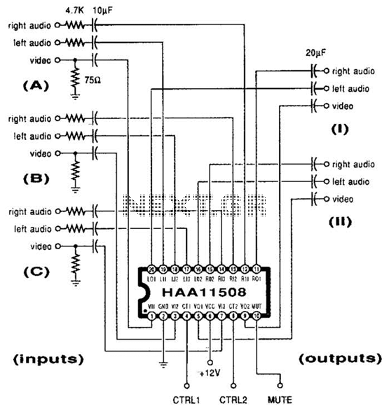
This channel selector selects video and stereo audio from any one of three different sources. The circuit should be constructed on a PC board with plenty of ground plane to minimize noise. The channel selector circuit is designed to facilitate...
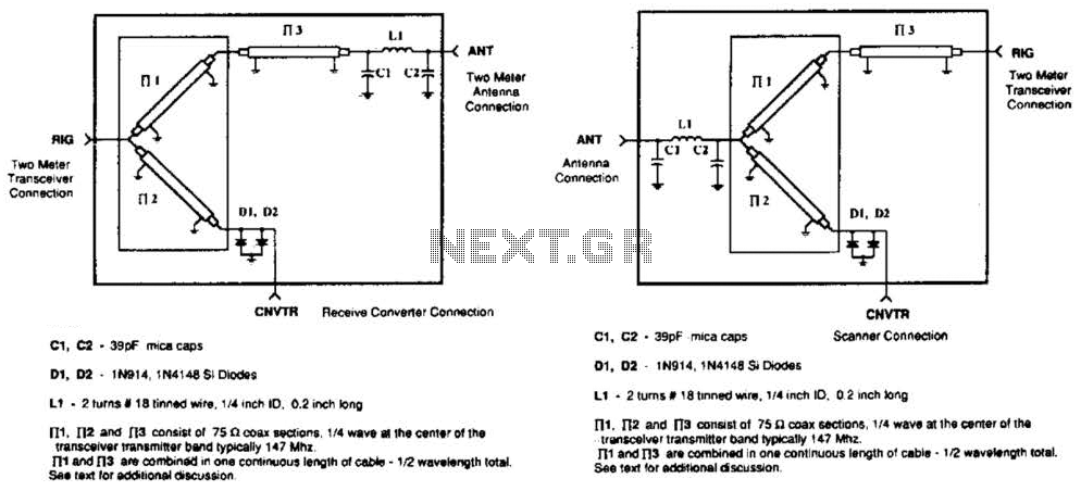
A pair of diodes and a quarter-wave transmission line are utilized as an automatic TR switch. D1 and D2 conduct during transmit periods, short-circuiting the scanner input. In this mode, the quarter-wave line appears as an open circuit. In...
AC level meters, such as VU meters, and DC level meters, such as signal meters, are used for measuring electrical signal levels. These devices feature a display consisting of nine red or green LEDs that represent the input level...
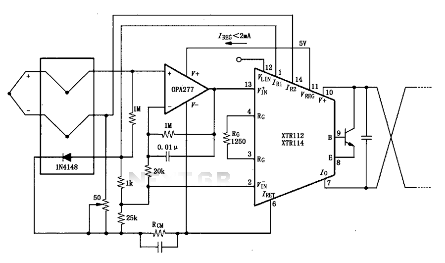
The OPA277 is configured as an inverting amplifier. This inverting amplifier utilizes high input impedance characteristics to minimize loop thermocouple offset drift. A 50-ohm potentiometer is included for calibration, allowing for the adjustment of the inverting input of the...
Warning: include(partials/cookie-banner.php): Failed to open stream: Permission denied in /var/www/html/nextgr/view-circuit.php on line 713
Warning: include(): Failed opening 'partials/cookie-banner.php' for inclusion (include_path='.:/usr/share/php') in /var/www/html/nextgr/view-circuit.php on line 713