
Adjustable High/Low Frequency Sine wave generator
The MAX038 function generator is a highly integrated device capable of producing a variety of waveforms, making it suitable for applications such as this ESR meter. The circuit design leverages its capability to generate sine, triangle, and square waves, with the output frequency determined by both external resistors and capacitors. The choice of 122 kHz is particularly advantageous for measuring the equivalent series resistance (ESR) of electrolytic capacitors, as it strikes a balance between reactance and measurement accuracy.
The ESR meter operates by applying an AC signal across the capacitor under test and measuring the voltage drop, which is proportional to the ESR. The use of a precision resistor in series with the capacitor allows for accurate current measurement, facilitating the calculation of ESR through Ohm's law. The TCA0372 op-amp serves to amplify the output signal to a level suitable for further processing or display, ensuring that the measurement is both clear and precise.
To accommodate various testing scenarios, the circuit includes options for frequency adjustment through a multiposition switch, allowing for rapid changes in testing conditions without the need for extensive reconfiguration. The design emphasizes ease of use and flexibility, making it suitable for both hobbyists and professionals in electronics.
Powering the circuit with a computer power supply or a multi-voltage transformer ensures that all necessary voltage levels are available, supporting the operational requirements of the MAX038 and associated components. The inclusion of smoothing capacitors and voltage regulators further enhances the stability and reliability of the circuit, minimizing noise and fluctuations that could affect measurement accuracy.
Overall, this circuit design effectively combines functionality and versatility, providing a reliable tool for assessing the health of electrolytic capacitors in various applications.This circuit uses the versatile MAX038 function generator. Although in this circuit some of the advanced characteristics of this IC are disabled, you can generate Sine, Triangle, Square waves (adjusting A0 and A1 pins see datasheet on if you want other waves, use a switch). I selected this particular frequency (122 Khz) because i needed a cheapo ESR-o-meter for my electrolytic capacitors to monitor their health as they have to discharge tens of amperes in less than 2 ms. At 122 KHz capacitive reactance is very low, and inductive reactance isn`t so high, so forcing a current (es 200mA, using a precision resistor) through a capacitor and reading AC voltage drop accross it gives me an estimation of ESR (Vdrop/current).
Of course inductive and capacitive reactance are still present, but negligible. The 122 khz 2V p-p sine wave is generated by the MAX038 IC, its frequency can be calculated by the formula Freq (MHz) = Iin(uA) / C6 (pf). Iin = 2, 5V / R1 (25Kohm default). So the freq is 0, 122 MHz. The resistor is for small adjustments, don`t go under 10000 Kohm or above 40000 Kohm because the accuracy will drop.
If you want multifrequency just use the multiposition switch with 820 pF, 8, 2 nF, 82nF, 820 nf for 122Khz range 12, 2Khz range 1220 Hz and 122 Hz. Fine tuning can be done adjusting R2, the frequency can vary from 1, 7x (Vfadj = -2, 4) to 0, 3x (Vfadj = 2, 4) of the main frequency (when fadj is at 0V).
The sine wave output is feed into a TCA0372 1/2 opamp to achieve a gain from 1 to 5 (2V p-p, 10 V p-p), adjust the potenziometer and into a TCA0372 2/2 opamp buffer stage also present on the same IC. Adjusting the frequency needs a frequency counter, so this circuit should be used on conjunction with a freq couter.
The max current is 1A, but i would suggesto to not go above 0, 5A to remain accurate. Needs a computer power supply with 12V, 5V, -5V, -12V, GND to be operated, if you don`t have one just use a multivoltage mains transformer (15 watt is enough) diode bridges (low current 1-2 Amps), smoothing capacitors 10000uF 16V, and voltage regulators such as LM7905 and LM7912. We aim to transmit more information by carrying articles. Please send us an E-mail to wanghuali@hqew. net within 15 days if we are involved in the problems of article content, copyright or other problems.
We will delete it soon. 🔗 External reference
Related Circuits
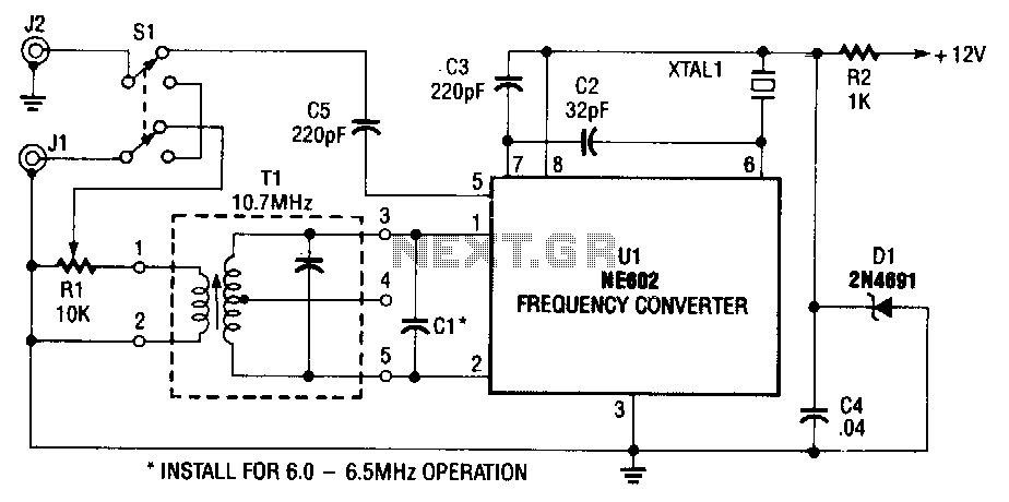
The NE602 (U1) includes oscillator and mixer stages. The mixer merges the oscillator signal with the input RF signal to generate signals whose frequencies are the sum and difference of the input frequencies. For instance, a 7.5-MHz signal received...
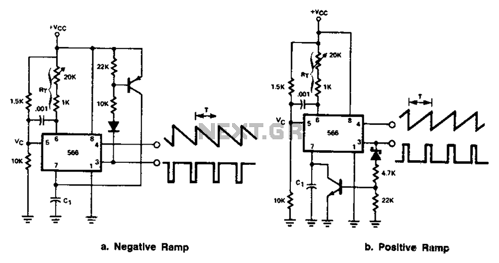
The 566 can be connected to either a positive or negative ramp generator. For a positive ramp generator, an external transistor is driven by the output pin 3. At the end of charging, C1 discharges quickly, allowing for immediate...
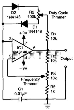
This relaxation oscillator circuit utilizes diodes to create charge and discharge paths for capacitor CI. The duty cycle is determined by resistor R2, while the frequency is controlled by resistor R4. The value of capacitor CI can be adjusted...
This is a simple frequency counter based on the microcontroller PIC16F84. Its maximum operating frequency is approximately 30 MHz, with a resolution of 10 Hz and low current consumption of 15 mA. The assembly process is straightforward. The device...
This circuit is designed to demonstrate high frequency and high voltage, capable of producing up to approximately 30 kV, depending on the transformer utilized. It is an economical and straightforward project, primarily using a standard TV flyback transformer. The...
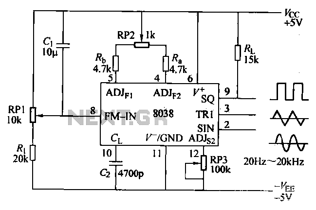
The ICL8038 function generator is an audio composition device that utilizes the ICL8038 integrated circuit. The resistance Ri potentiometer RP1 is used to determine the flow potential. Typically, the output is set to approximately 2Vcc / 3. Lowering the...
Warning: include(partials/cookie-banner.php): Failed to open stream: Permission denied in /var/www/html/nextgr/view-circuit.php on line 713
Warning: include(): Failed opening 'partials/cookie-banner.php' for inclusion (include_path='.:/usr/share/php') in /var/www/html/nextgr/view-circuit.php on line 713