
Square-Wave Generator
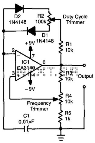
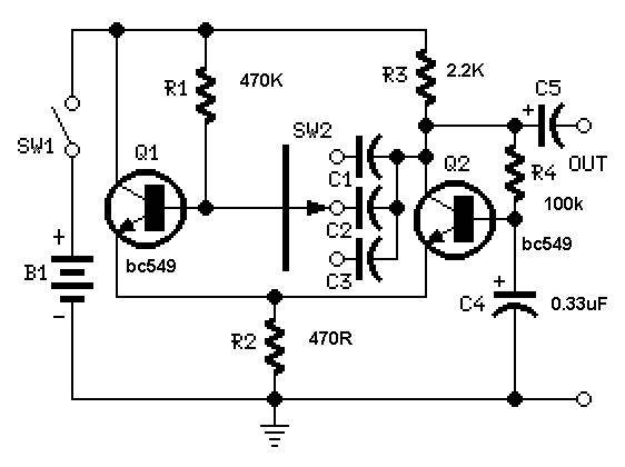
The relaxation oscillator circuit operates by alternately charging and discharging a capacitor, producing a square wave output. The diodes in the circuit play a crucial role in directing the current flow during the charge and discharge cycles. When the capacitor CI charges through resistor R4, it accumulates voltage until it reaches a predefined threshold. At this point, the diodes allow the capacitor to discharge rapidly, creating a pulse. The cycle then repeats, resulting in a continuous oscillation.
The duty cycle, defined as the ratio of the time the output is high to the total period of the waveform, is influenced by the resistance value of R2. A higher resistance will increase the time it takes for the capacitor to charge, thereby increasing the duty cycle. Conversely, a lower resistance will result in a shorter charging time, decreasing the duty cycle.
The frequency of oscillation is primarily determined by the RC time constant, which is a product of the resistance (R4) and capacitance (CI). By varying R4, the frequency can be adjusted within the specified range of 300 to 3000 Hz. Additionally, changing CI allows for further tuning of the frequency, providing flexibility in applications where precise timing is necessary.
This type of oscillator is commonly used in applications such as audio signal generation, timer circuits, and various other electronic devices that require a stable oscillating signal. Proper selection of components is essential to achieve the desired performance characteristics, including stability, frequency accuracy, and duty cycle. This relaxation oscillator circuit uses diodes to produce charge and discharge paths for CI. The duty cycle is set vi a R2 and the frequency via R4. CI can be varied to vary the frequency range, which, for this circuit is approximately 300 to 3000 Hz. 🔗 External reference
Related Circuits
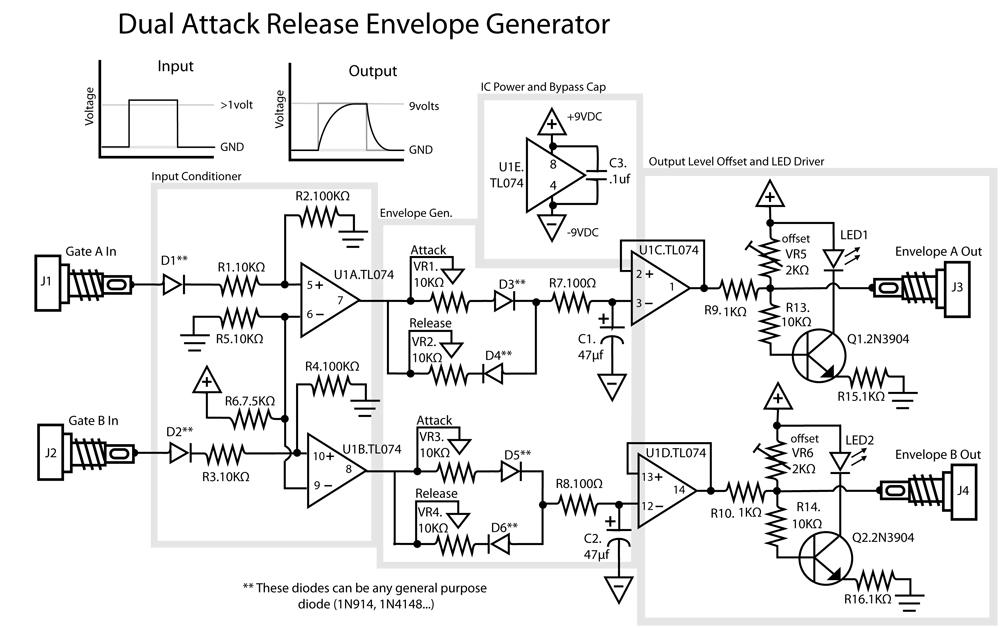
This is a dual Attack/Release envelope generator that has been added to the Modular Benjolin design. While not essential, it provides enjoyable functionality, particularly when used alongside the modular rungle bit output mod. The circuit is straightforward, making it...
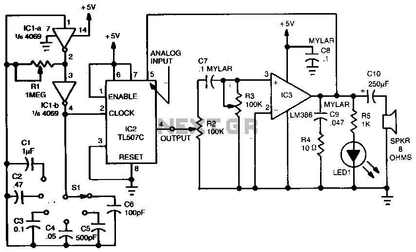
A variable dock-pulse generator consists of two sections of IC1, which is a 4069 CMOS hex inverter, along with resistor R1, switch S1, and capacitors C1 through C6. By adjusting R1 and switching one of the capacitors into the...
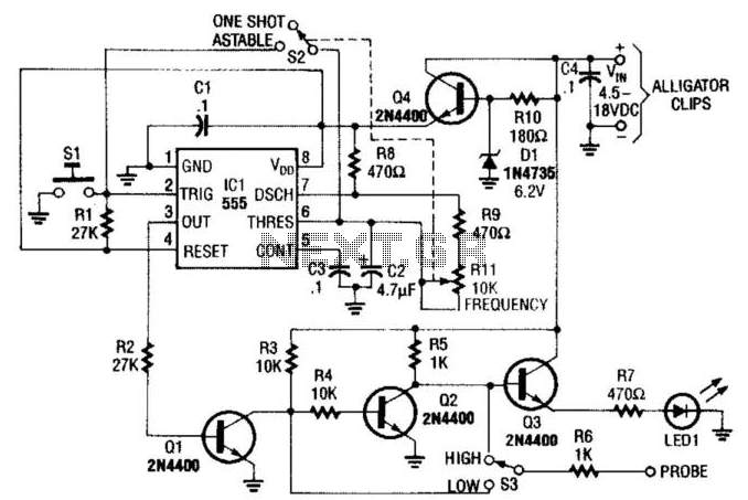
This pulse generator is constructed using a 555 timer integrated circuit (IC) and can be integrated into a probe for logic troubleshooting. Resistor R1 controls the frequency, providing a range of approximately 5 to 200 Hz. Capacitor C2 can...
The timing must be exact to get those high voltage spikes. I used a tiny magnet on the rotor, that triggered a reed switch allowing the relay to pulse the energy from the recovery coil to the primary battery....
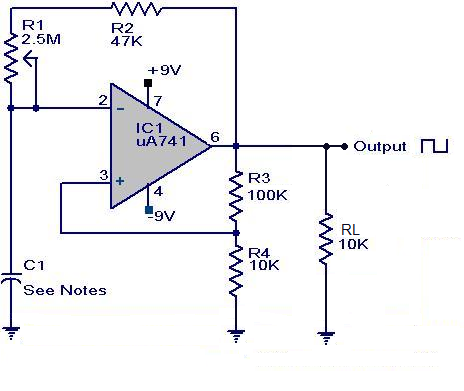
A square wave generator using the UA741 integrated circuit is presented. This circuit employs positive feedback for Schmitt trigger action and negative feedback to measure the waveform timing. Initially, it is assumed that the output is high and capacitor...
A useful feature of this circuit is that the frequency can be changed by modifying the capacitor value. A switch can be added to select between various frequencies. This circuit utilizes a capacitor in conjunction with an oscillator to determine...