
Low power audio amplifier

The amplifier circuit is designed to provide robust audio amplification while accommodating a wide range of supply voltages, making it versatile for various applications, including those reliant on renewable energy sources like solar panels. The use of a potentiometer allows for user-friendly volume control, enabling adjustments to audio output levels based on user preference or environmental conditions.
Capacitor C3 plays a critical role in maintaining the stability of the amplifier by decoupling high-frequency noise from the power supply, ensuring that the amplifier operates efficiently without interference. Additionally, it contributes to low-frequency roll-off, which helps to prevent unwanted low-frequency signals from affecting the audio quality. The power supply ripple rejection capability of C3 is essential for maintaining clean audio output, especially in environments where power supply fluctuations may occur.
Capacitor C4, being an electrolytic capacitor, is specifically chosen for its ability to handle the coupling of audio signals to the output stage. It is essential for transferring the amplified audio signal to the speaker while blocking any DC component that could potentially damage the speaker. The specified impedance range of 8 to 32 ohms for the speaker ensures compatibility with a variety of speaker types, allowing the amplifier to drive speakers efficiently and produce high-quality sound output.
Overall, the design of this amplifier circuit, with its careful selection of external components, ensures reliable performance across a range of operating conditions, making it suitable for both portable and stationary audio applications.The amplifier operates from supplies ranging up to 12 volts, and operates (with reduced volume) from supply voltages as low as 1.8 volts without having distortion rise to unacceptable levels. (Its power requirements make it suitable for solar-cell application.) Components external to the integrated circuit, Ul, consist of four capacitors and a potentiometer for volume control.
Capacitor C3 is for decoupling, low-frequency roll-off, and power-supply ripple rejection. Capacitor C4 is an electrolytic type that couples the audio output to an 8 to 32 ohm speaker that is efficient.
Related Circuits
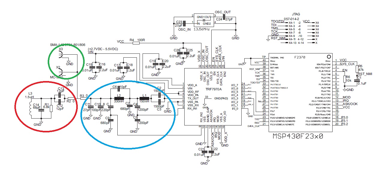
The "green area" is designated for the placement of the TRF7970A's antenna, which should be connected between two 0-ohm resistors. The antenna can be constructed step by step following the guidelines in the document "Antenna Matching for the TRF7960...
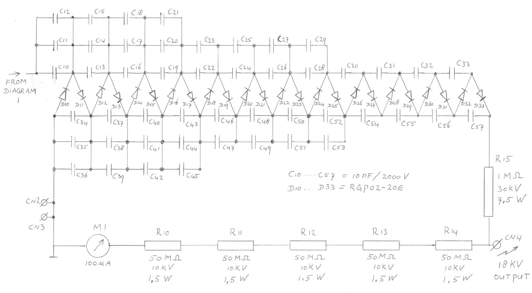
Each subsequent stage adds 1700 volts, resulting in more than 20 kV with 12 stages. However, this voltage can only be achieved when the output of the cascade is unloaded. The described circuit appears to be a high-voltage cascade generator,...
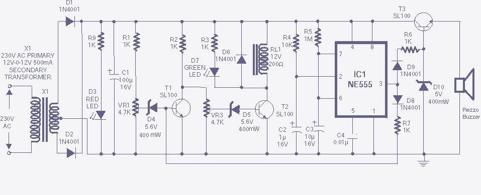
The high and low voltage cut-off with delay and alarm circuit, along with its circuit diagram, is explained in this post. The high and low voltage cut-off circuit is designed to protect electrical devices from damage caused by excessive voltage...
This circuit performs a rapid battery test without requiring an external power supply or costly moving-coil voltmeters. It features two ranges: when switch SW1 is set as indicated in the circuit diagram, the device can test batteries ranging from...
The C620 lathe Y-conversion includes a power-saving circuit designed for controlling the motor's reversing functionality. This system is applicable to machines such as the C620, C630, and CW61100A lathes, as well as radial drilling and milling machines. The C620 lathe...
The first schematic is designed for individuals who exclusively purchase electronic components from Radio Shack. It allows for a straightforward shopping experience, enabling one to acquire all necessary parts in-store. For the heat sink, it is recommended to visit...