
Small class b audio amplifier circuit diagram
The circuit operates on a dual power supply, providing both positive and negative voltages to accommodate the Class AB amplification, which is essential for minimizing distortion and achieving high fidelity in audio applications. The use of an operational amplifier (IC1) ensures that the input audio signal is accurately amplified while maintaining signal integrity. The selection of components, including capacitors and resistors, is critical for setting the gain and frequency response of the amplifier. Capacitor C1 serves to block any DC offset from the input signal, allowing only the AC audio signal to pass through to the amplifier stage.
The push-pull configuration of Q1 and Q2 allows for efficient amplification of both halves of the audio waveform, which is crucial for producing a clean and powerful output. The Darlington pairs formed by Q1 with Q4 and Q2 with Q3 increase the current gain, allowing the circuit to drive heavier loads such as loudspeakers without significant distortion. The thermal management of the output transistors is vital, as excessive heat can lead to thermal runaway and potential failure of the transistors. Heat sinks or other cooling methods should be employed to ensure reliable operation.
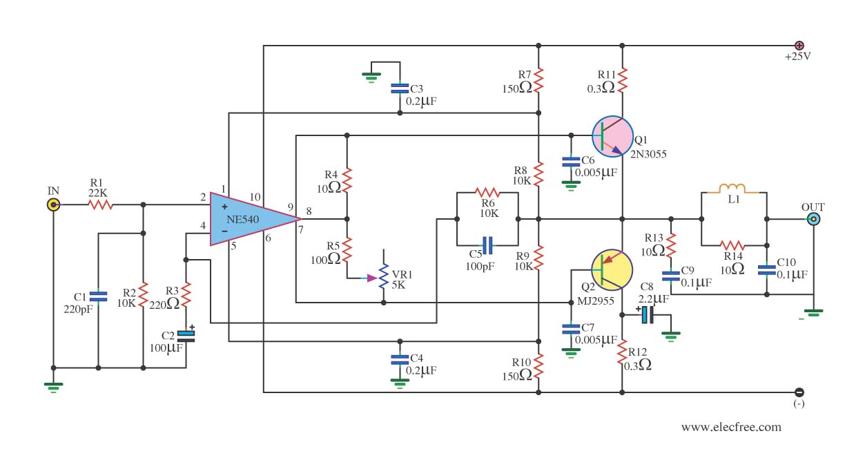
This design is particularly advantageous for beginners in electronics, as it provides a straightforward approach to building a functional audio amplifier while allowing for further modifications and enhancements. The inclusion of tone controls (volume, bass, and treble) adds versatility to the amplifier, enabling users to tailor the audio output to their preferences. Overall, this OCL Class AB amplifier circuit exemplifies a practical application of fundamental electronic principles in audio engineering.When feed power supply reach the circuit and feed input signal come in. The sound signal change C1 and R1 for signal coupling and eradicate noise oscillator go out. From that time go to reach input pin 3 non inverting of IC1. Which be op-amp IC boost up signal give the power goes up in order to go to drive give Q1 and Q2 work. Which IC1 will haveexpansion rate at 15 times can calculate from (R3/R2)+1. From that time signal that enlarge already go out pin 1 of IC1 go to feed give with Q1 and Q2 which build the circuit model put-pull do signal both of section expansion positive and the section negative. By Q2 enlarge signal section way positive and build output give with Q3 which Q2 and Q3 this each other darlington for have the expansion ratio more and more.
Part Q1 signal boost up section way negative and build output signal give Q4. Which Q1 and Q4 build the circuit model Darlington also output signal of Q4 and Q3 and go out pin way E come to total up signal section positive and the section negative already go out still a loudspeaker. Because of while the circuit will work to is born the heat Q3 and Q4 thus then must add let off the heat gives with Q3 and Q4 with.
A younger brother of me receives Electronics KIT that older. It is Power Amp OCL 25w With IC STK032. But have no the circuit. I has looked into already be model to follow the circuit. When see already a button fines to decorate Volume, Bass and Treble of the sound has completely. And still the circuit integrated amplifier model OCL Class AB as well although will have 25Watt drives. But have a voice good loud moderately completed convenient for a novice, build good easy please sir. Today have Older power Amplifier OCL Circuit come to give friends get see in rows the way again. By it has the electric power about 35W at 8ohm loudspeakers and use Voltage Supply +25V and -25V at Current 2A.
Which cheap systematize the sound is Class AB. By this circuit use the integrated circuit number NE540 replace the transistor has many. Then use power Transistor 2N3055 and MJ2955 at output. The detail is other invite a friend has seen in the circuit, be lucky sir. 🔗 External reference
Related Circuits
This circuit will allow you to connect any tape recorder that has a mic and remote input to a phone line and automatically record both sides of a conversation whenever the phone is in use. You will need to...
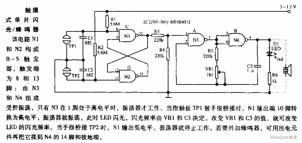
In the circuit, N1 and N2 form the RS flip-flop, with the trigger inputs located at pins 8 and 13. N3 and N4 create a controlled oscillator that operates only when pin 1 of N3 is high. When the...
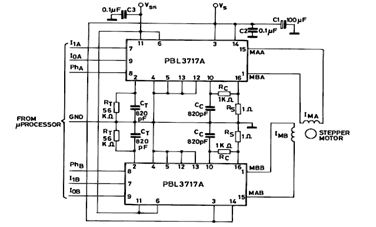
The diagram below illustrates a Two Phase Bipolar Stepper Motor Driver utilizing the PBL3717A. It depicts two PBL3717A integrated circuits (ICs) that control and drive two bipolar stepper motors. The Two Phase Bipolar Stepper Motor Driver circuit is designed to...
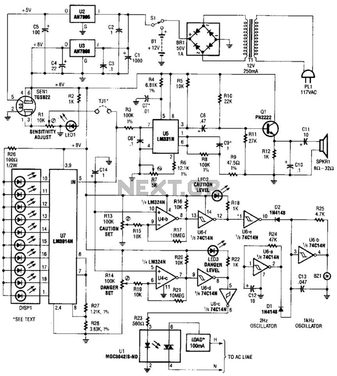
A gas sensor (TGS823 from Allegro Electronics, Cornwall Bridge, CT 06754) conducts in the presence of explosive gases. U5 is a voltage-to-frequency converter that produces a frequency proportional to the sensor conductance. The output frequency ranges from 100 Hz...
A thermistor is utilized in the circuit for heat sensing, while two 5K variable resistors are incorporated to calibrate the circuit for activating the relay at the desired temperature. The inclusion of a 1N4007 diode across the relay serves...
This circuit is a simple IR detector for testing IR remote controllers. The circuit is based on one phototransistor which receives the IR beam. The NPN transistor works as an amplifier which feeds current to the LED. When this...