
Advance Burglar alarm from dual-op amp
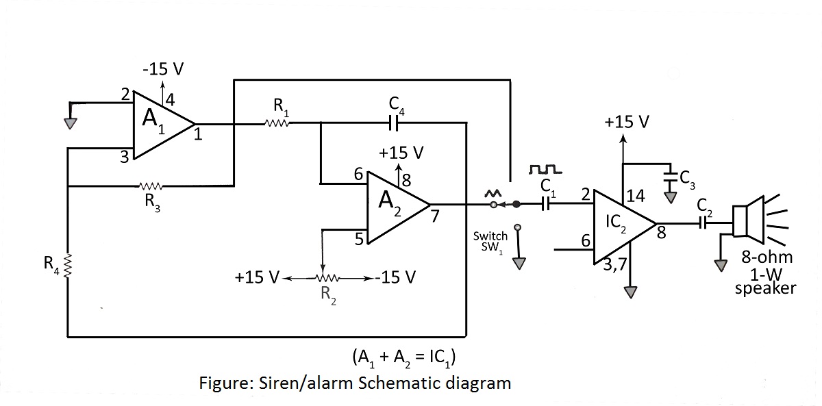
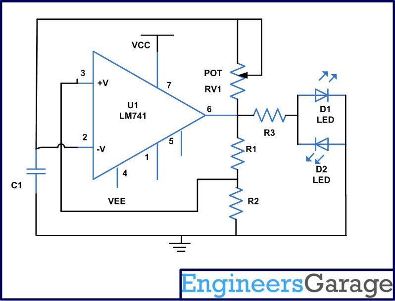
The burglar alarm system utilizes a dual operational amplifier (op-amp) to enhance its monitoring capabilities. The circuit typically consists of two main sections: the sensing unit and the alarm triggering unit.
The sensing unit employs a dual op-amp configuration to amplify signals from various sensors, such as motion detectors or door/window contacts. When a sensor is triggered, it generates a low-level voltage signal that is fed into the non-inverting input of the first op-amp. This op-amp is configured as a voltage amplifier, boosting the signal to a level suitable for processing. The gain of this amplifier can be adjusted by selecting appropriate resistor values in the feedback loop, allowing for customization based on the sensitivity required for the specific application.
The output of the first op-amp is connected to the inverting input of the second op-amp, which is configured as a comparator. This op-amp compares the amplified signal against a predetermined reference voltage set by a voltage divider circuit. If the amplified signal exceeds the reference voltage, the output of the comparator switches from low to high, triggering the alarm.
The alarm triggering unit may include additional components such as a relay or a transistor switch to activate a siren or notification system. The relay is typically connected to the output of the second op-amp, allowing it to control high-current devices while isolating the low-power op-amp circuit.
Furthermore, the circuit can include features such as delay timers, which prevent false alarms due to temporary disturbances, and reset mechanisms that allow the system to be easily rearmed after an alarm event. Overall, the use of a dual operational amplifier in a burglar alarm circuit provides enhanced sensitivity and reliability, making it an effective solution for security monitoring applications.Device such as burglar alarms and sirens, whose basic purpose is to monitor tested circuit diagram with description of burglar alarm alarm using dual operational amplifier. 🔗 External reference
Related Circuits

Signals always involve at least two paths to complete a circuit. For instance, when electrons travel down the center lead of a guitar cable, an equivalent number return on the shield. The shaft of the plug connects to ground...
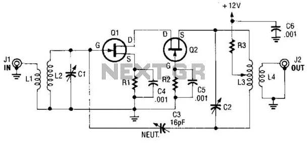
A cascode amplifier using two MOSFETs is illustrated in the diagram. L2C1 and L3C2 resonate at the operating frequency. The circuit offers advantages such as high gain, low noise figure (NF), and excellent linearity. Q1 and Q2 can be...
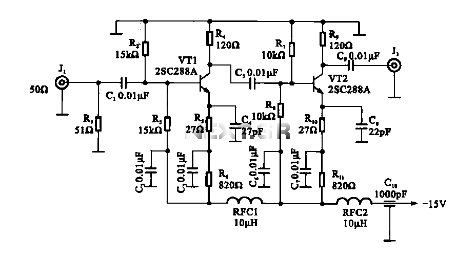
The circuit consists of a two-stage common emitter amplifier, which serves as a practical wideband amplifier. It utilizes capacitors for coupling between the input and output stages. The emitter decoupling capacitor, C4, is employed to eliminate AC negative feedback,...
The closer the two transistors are matched, the better the performance. It is advisable to use TIP41 and TIP42 transistors, which are closely matched NPN and PNP power transistors with a dissipation rating of 65 watts each. If a...

This is a simple yet effective burglar alarm circuit designed to be mounted on windows for detecting break-ins. The circuit employs a fine wire element arranged as a network within the window glass for sensing any breach. Under normal...
An astable multivibrator is an electronic device that continuously alternates between two states in its output. When one state is high, the other is low. This characteristic is useful for generating a continuous stream of pulses without the need...