
Advantages and challenges of third-overtone IC crystals
.jpg)
nal reactive elements and higher gain. Most crystals use the fundamental thickness-shear vibration mode of AT-cut quartz. The practical upper limit of fundamental operation is around 50 MHz because the fundamental resonant frequency is inversely proportional to thickness. Frequencies higher than 50 MHz become too thin to handle during the manufacturing process. While a few crystal manufacturers can make fundamental crystals to 600 MHz or more using the inverted mesa process, 3OT manufacturers are more prevalent.
The 3OT is a crystal mode that resonates at three times its fundamental frequency. There are in fact an infinite number of odd harmonics that exist on the same quartz plate. The first, third and fifth harmonics are shown in Figure 1a with some anharmonic modes or spurs shown in between. Spurs are by-products of other vibrational modes and a good crystal manufacturer makes sure that these are minimized.
G‚ The AT-cut crystal has the equivalent circuit (see Fig. 1b) of a series RLC for the fundamental and each harmonic mode plus a capacitor, C0, in parallel due to the electrodes. The 3OT series resistance, Rs, is more than three times that of the fundamental mode. Its series capacitance, Cs, is nine times less. This lower Cs in the 3OT will make tuning or calibration harder in the oscillator. If the crystal is too far off nominal frequency, there is less chance to electrically correct this in the oscillator.
The 3OT has higher Q, which is the most important feature next to its higher frequency, as it results in better jitter and phase noise. Because the 3OT plate is as thick as a fundamental one-third its frequency, it is structurally robust with very good aging characteristics.
G‚G‚G‚G‚G‚G‚G‚G‚G‚G‚G‚G‚G‚G‚G‚G‚G‚G‚G‚G‚G‚G‚G‚G‚G‚G‚G‚G‚G‚G‚G‚G‚G‚G‚G‚G‚G‚G‚G‚G‚G‚G‚G‚G‚G‚G‚G‚G‚G‚G‚G‚G‚G‚G‚G‚G‚G‚G‚G‚ G‚G‚G‚G‚G‚G‚G‚G‚G‚G‚G‚G‚G‚G‚G‚G‚G‚G‚G‚G‚G‚G‚ Fig. 1: The first, third, and fifth harmonics are shown inG‚(a) with some anharmonic modes or spurs shown in-between.
The AT-cut crystal has the equivalent circuit, shown in (b), of a series RLC for the fundamental and each harmonic mode plus a capacitor, C0, in parallel due to the electrodes. A 3OT oscillator design is more complicated. In general a crystal oscillator will always run on the fundamental, as it is the lowest resistance mode.
While the 3OT has the next lowest mode in resistance, to operate on it, the fundamental must be suppressed. In Fig. 2 the top circuit is a fundamental Pierce crystal oscillator, a stable and common configuration for IC oscillators.
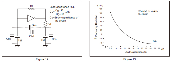
It consists of an inverting linear amplifier and two `PI` capacitors, C1 and C2, on either side of the crystal. The resistor shown can standalone or represent the output resistance of the inverter. The crystal is calibrated to operate with a capacitive load so it looks slightly inductive and therefore resonates with the two PI caps - which from an AC point of view are in series.
Around the loop there is 360G‚ ° of phase shift to meet one of Barkhausen`s criteria. The inverter contributes a little more than 180G‚ ° phase lag, the R-C accounts for a little less than 90G‚ °, and the crystal (operating inductively) with the second PI cap, contributes a little more than 90G‚ °. With enough gain to overcome the crystal resistance, and feedback elements, it meets the second of Barkhausen`s criterion and it will oscillate.
Fig. 2: In (a) the Pierce crystal oscillator is considered a stable and common configuration for IC oscillators. In (b) is a 3OT oscillator with a fundamental rejection circuit. The bottom circuit of Fig. 2 is a 3OT oscillator with a fundamental rejection circuit. An LC tank replaces the first PI capacitor in the fundamental oscillator. The tank is designed to be capacitive at the 3OT frequency and inductive at the lower fundamental frequency.
In this way, the fundamental mode will not run because the phase shifts around the loop will not add up to be 360G‚ °, but the phase conditions for the 3OT will be correct when the tank is capacitive. Oscillation will occur provided that there is sufficient gain to overcome the increased resistance of the 3OT crystal.
Another option is to put a high-pass filter in with the amplifier, starving the gain at the fundamental but allowing sufficient gain at the 3OT frequency. In this way an LC selector network is unnecessary though it may take more than one IC with different high pass filters to cover wide frequency ranges.
The PI caps are built into the IC so only the crystal is required externally. 3OT IC oscillators also integrate inductors for the tanks to select the 3OT or create high pass filters to reject the fundamental. Increased gain, commonly referred to as negative-R, is required for the 3OT because of the higher resistance.
Negative-R however is not flat across a frequency range. The IC manufacturer must not only guarantee that there is enough gain at the desired frequency, but there must be enough gain with C0 across its terminals. Too little gain may cause starting problems. The required gain can be calculated with the following formula. 🔗 External reference
Related Circuits
The drive level of a crystal unit is indicated by the operating power level or current consumption. Operating the crystal unit at excessive power levels can degrade its characteristics, potentially causing frequency instability or physical failure of the crystal...
Electronics tutorial about quartz crystal oscillators, including harmonic, overtone, Pierce oscillator, and crystal quartz oscillator circuits. Quartz crystal oscillators are vital components in modern electronics, providing stable frequency references for a variety of applications. They utilize the piezoelectric properties of...
Understanding how quartz-crystal resonators operate can lead to designing crystal oscillators with improved stability and better noise performance. Quartz-crystal resonators function based on the piezoelectric effect, where mechanical stress applied to a quartz crystal generates an electrical charge. This property...
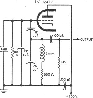
To update the fundamental oscillator circuits, simply replace the transistors with tubes. Alternatively, if one owns a vintage vacuum tube radio, it may be of interest to learn about historical practices. In general, the foundational principles of electronic circuits...
A brief note explaining the process of substituting crystal and ceramic resonator clock circuits with silicon oscillators, while emphasizing the technical benefits these devices provide in microcontroller clock applications. Silicon oscillators serve as an effective alternative to traditional crystal and...

Another frequency-determining device is the crystal. The crystal may be used with a tank circuit, or it may function independently. Crystals exhibit a characteristic known as the piezoelectric effect, which is the property of a crystal that allows mechanical...