
Aeration ponds remind circuit
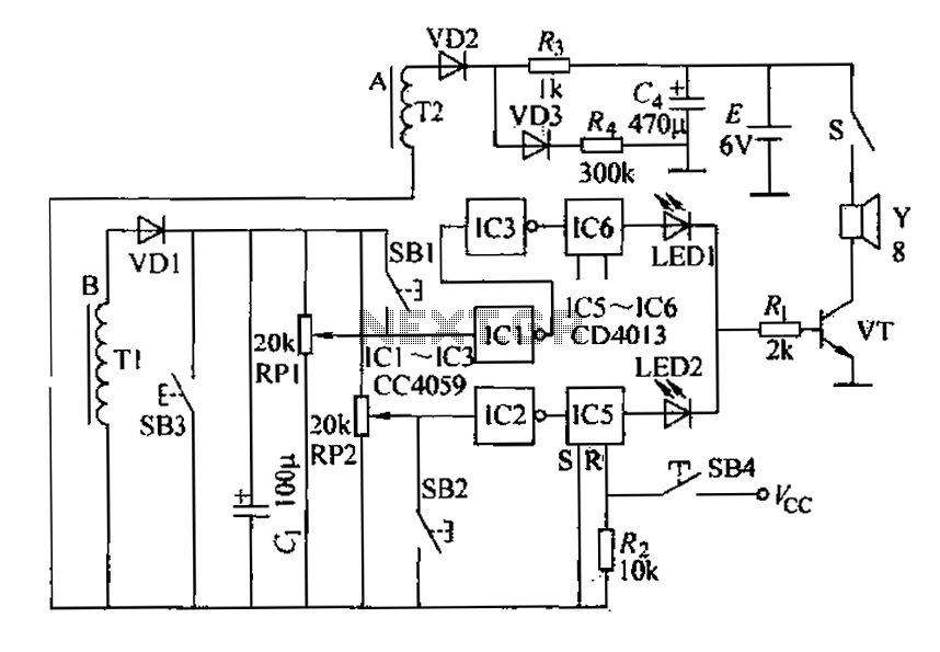
In the event of an overload or partial short circuit, if a phase is lost, the output voltage from capacitor C1 increases, triggering the alarm via IC1, which locks the alarm and activates LED1 as an indicator. When a phase is operational, if a phase loss occurs, the total current rises, causing the voltage across C to increase, which then triggers IC1 to activate the alarm circuit. If the phase is maintained, the voltage across capacitor C1 remains at zero. The output from IC2 triggers the alarm when the motor experiences burnout due to capacitance loss or excessive voltage. This failure phenomenon has been observed infrequently.
In addition to the aforementioned alarm conditions, IC2 also monitors for off-axis light load and power failure alarms, which are common issues in inland pond aerators. Adjusting RP2 allows the input voltage to IC2 to be slightly higher than its flip voltage during normal operation. When an off-axis condition occurs, the load significantly decreases, causing a voltage drop across capacitor C. This results in the input voltage to IC2 falling below the trigger level, prompting IC2 to flip and instruct IC5 to activate the alarm, which also self-locks. The input from IC2 transitions from high to low during power loss, similarly triggering the alarm output.
Buttons SB1, SB2, and SB3 are used for testing the alarm system's components whenever the aerator is powered on, ensuring all parts are functioning correctly. IC5 and IC6 are single-shot devices that provide rapid indication of fault types when an alarm condition arises, allowing for quick user response. If the system requires a reset, pressing button SB4 resets the CC4013 dual trigger. A small 6V battery power supply (E) is utilized, with diode VD2 supplying several milliamps of quiescent current to maintain circuit operation during normal conditions. IC1 to IC3 are six inverters from the 4049 series, while IC5 and IC6 consist of a pair of D flip-flops from the CC4013 series, supporting a 2.8kW motor with approximately 250 turns for Tl and around 600 turns for T2.A, B is oxygen electromechanical motive in the two-phase three-phase power. Tl, T2 is wound around the outside of the two current sensing coil. When the normal power supply, Tl , rectifier T2 to VD1, VD7, Cl, G consisting of circuitry in the filter capacitor C, can be maintained on certain electrical voltage, RP1, RP2 as two potentiometers, Ri of phase, overload, partial short circuit, motor burnout alarm control system. During normal operation the potential RP1 contact position slightly lower in IC1 flip voltage, IC1 outputs a high level, IC3 output low.
RP2 potentiometer contact potential slightly higher than the voltage of IC2 flip, the same output low. When the over load, partial short circuit occurs and when no phase, Cl filtering the output voltage increases, lcl flip, the alarm is energized and locked alarm, LED1 emitting tips.
When the phase is running. If the phase is not the phase, the total current increases in the South, C, filtering the voltage increases, 1C1 flip trigger an alarm circuit, if the phase is the phase. C1 capacitor voltage is ov. IC2 flip portion of the output to trigger alarm level, an alarm, when the motor burned before C- capacitance loss of power or higher voltage, similarly lCl or IC2 flips trigger an alarm circuit, in actual use, this failure occurs We have demonstrated in front of a phenomenon.
This occurs less. IC2 addition to the above case the alarm, but also on the aerator off-axis light load, power failure alarm, which is inland in ponds most accident-prone. RP2 adjust the IC2 input terminal voltage slightly higher than the IC2 flip voltage is normal. When the off-axis occurs because the load will significantly reduce light, C, smoothed voltage drop, 1C2 input voltage falls below the trigger, IC2 immediately flip, IC5 instructs an alarm is triggered and self-locking; in the power of the IC2 input from the high case goes low.
Similarly the output alarm. SB1, SB2, SB3 for the three button switch, press SB1, SB2, SB3 check whether packets are part of an alarm every time you turn aerator police, the circuit simple safety checks to determine whether all parts properly. IC5, IC6 two single-shot, when an alarm condition occurs when a user can quickly inform the type of fault, and remove.
When not properly reset, press the button SB4 let CC4013 two triggers reset. E is small 6V power supply battery, VD2 provides several mA quiescent current consumption of the circuit to supplement the circuit during normal operation. IC1-IC3 is a six inverters 004069, IC5, IC6 is one pair of D flip-flop CC4013t 2.8kW motor I. 1 about 250 turns, L around 600 turns.
Related Circuits
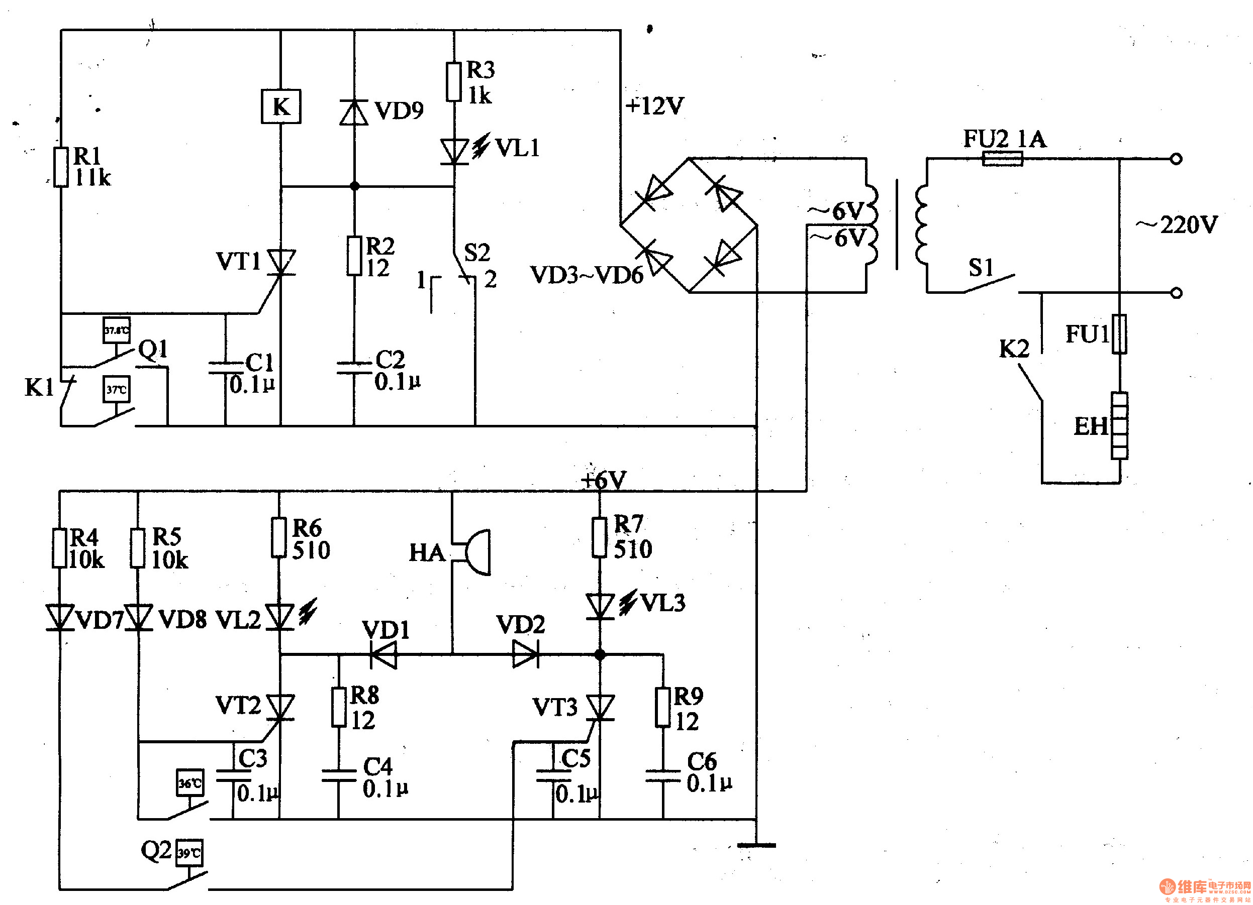
The egg hatching incubator circuit comprises a power supply circuit, a constant temperature control circuit, and a sound and light alarm circuit, as illustrated in Figure 4-7. The power supply circuit includes a power switch (S1), a fuse (FU2),...
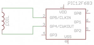
How to build your own RFID system using a microcontroller. This schematic is very simple. Building a Radio Frequency Identification (RFID) system using a microcontroller involves several key components and a straightforward schematic design. The essential elements of an RFID...
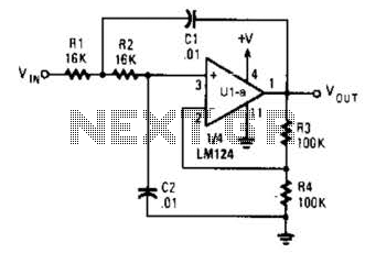
The circuit presented has a cutoff frequency of approximately 1 kHz. The resistors R1, R2, and capacitors C1, C2 can be adjusted to achieve any desired frequency. The circuit is designed as a filter, likely a low-pass or high-pass filter,...
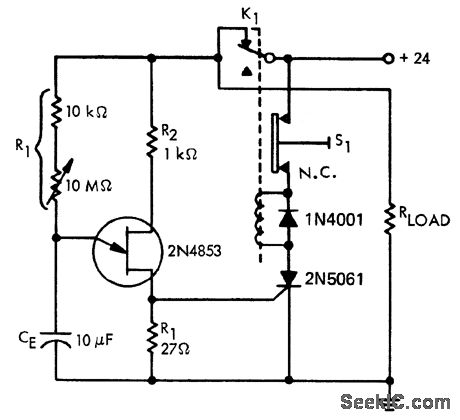
A time delay circuit utilizing a Unijunction Transistor (UJT). The maximum time delay is adjustable via a 10 MΩ potentiometer, allowing the time delay to be configured from less than one second to approximately 2.5 minutes, as referenced by...
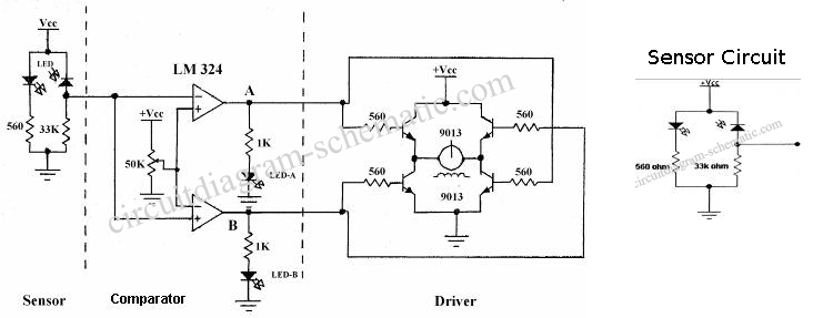
The following circuit illustrates the sensor circuit of an analog line follower robot. Features include control by a microcontroller and a sensor circuit. The sensor circuit for an analog line follower robot is designed to detect the presence of a...
The multifunction circuit primarily refers to its capability to operate in three modes: "delayed pull," "time release," and "delayed cycle." The term "delay" indicates that the relay is energized after a predetermined time; however, the relay does not activate...