
Time delay circuit using a UJT
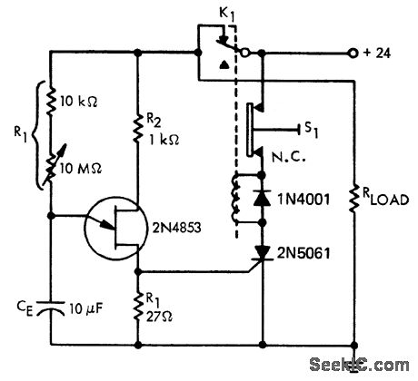
The time delay circuit based on a UJT operates by charging a capacitor through a resistor network, where the UJT serves as a switching element. The circuit primarily consists of a UJT, a timing capacitor, a resistor, and a potentiometer for fine-tuning the delay.
When power is applied, the capacitor begins to charge through the resistor, and the time it takes to reach the UJT's triggering voltage determines the delay. The 10 MΩ potentiometer allows for a wide range of resistance values, enabling precise control over the charge time and, consequently, the delay duration.
The capacitor voltage increases gradually until it reaches the peak point of the UJT's characteristic curve, at which point the UJT turns on, discharging the capacitor and triggering the connected load. This action can be utilized in various applications, such as timers, delay switches, or pulse generators.
The circuit's design should include proper biasing for the UJT to ensure stable operation, and considerations for component tolerances are necessary to maintain the desired timing accuracy. Additionally, the selection of the capacitor value and the resistor in conjunction with the potentiometer will influence the overall timing range and performance of the circuit.
For optimal functionality, it is also advisable to incorporate bypass capacitors to filter out any noise that may affect the timing accuracy, and to ensure that the circuit is housed in a suitable enclosure to prevent external interference.Time delay circuit using a UJT. Maximum time delay is set by the 10M pot. Time delay can be set from less than a second to approximately 2. 5 minutes (courtesy Motorola Semiconductor Products Inc. ). 🔗 External reference
Related Circuits
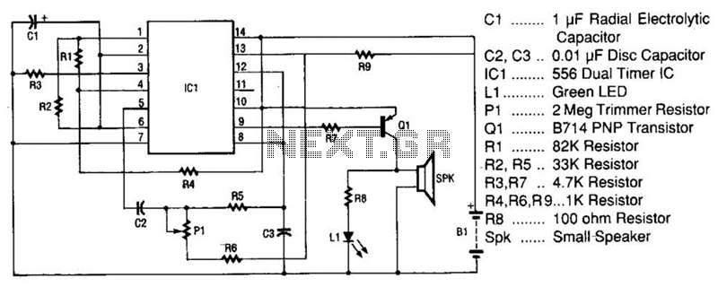
The space-age sound device utilizes a 556 dual timer integrated circuit (IC) to generate a phasor sound. This IC consists of two 555 timer circuits within a single 14-pin package, as depicted in the schematic. Each timer operates in...
The following circuit illustrates the circuit diagram of a motor control unit. This circuit is based on the LM317 integrated circuit. Features include diodes that protect the regulator. The motor control unit circuit utilizes the LM317 voltage regulator to provide...
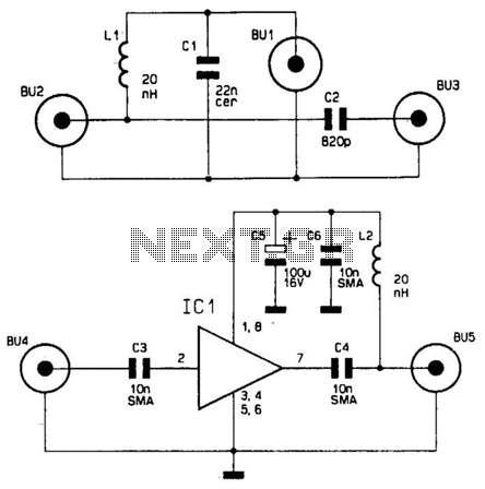
This wideband antenna preamplifier has a gain of approximately 20 dB from 40 to 860 MHz, covering the entire VHF, FM, commercial, and UHF bands. A phantom power supply delivers DC power to the preamplifier through the coaxial cable...
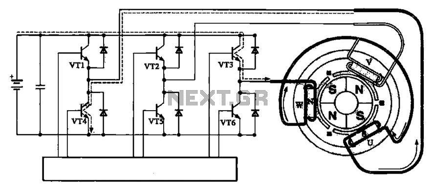
The brushless motor consists of a rotor, a stator, and a drive circuit. The relationship between the brushless motor rotor, stator, and drive circuit is illustrated in the accompanying figure. In the initial state, VT3 and VT4 are conducting,...
The Hopping Decoder is utilized in conjunction with the Hopping Encoder device to decode address data, key data, and rolling data. It employs the DES24 encryption algorithm for decoding. Each time the Hopping Encoder key is activated, the rolling...
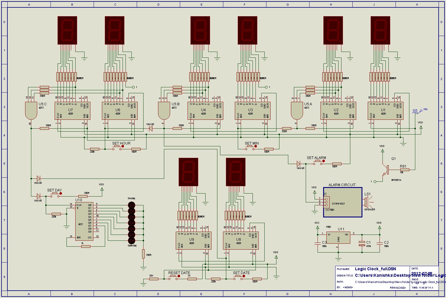
The count advances as the clock input transitions to high (on the rising edge). Each output from Q0 to Q9 activates sequentially as the counting progresses. For specific functions, such as flash sequences, outputs may be combined using diodes....
Warning: include(partials/cookie-banner.php): Failed to open stream: Permission denied in /var/www/html/nextgr/view-circuit.php on line 713
Warning: include(): Failed opening 'partials/cookie-banner.php' for inclusion (include_path='.:/usr/share/php') in /var/www/html/nextgr/view-circuit.php on line 713