
Air Flow Detector
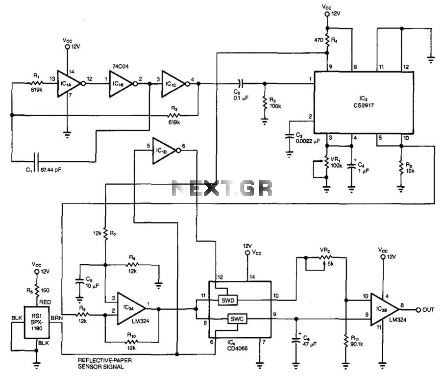
The circuit operates on the principle of thermal resistance variation caused by airflow. The incandescent lamp's filament serves as both the heating element and the sensing element. The constant current source is critical as it ensures that the filament reaches a stable temperature, allowing for consistent operation. The heating effect causes the filament to reach a temperature where its resistance is predictable and can be accurately measured.
As airflow occurs over the filament, the cooling effect results in a decrease in temperature, which in turn lowers the resistance of the filament. This change in resistance is monitored by a comparator circuit. The comparator is configured to compare the voltage across the filament against a reference voltage. When the airflow cools the filament sufficiently to change its resistance, the voltage drop across the filament will fall below the reference voltage, triggering the comparator to activate an output signal.
In practical applications, the output of the comparator can drive an LED, providing a visual indication of airflow presence. For more advanced applications, the output can also be interfaced with an analog-to-digital converter (ADC) or a digital meter. This allows for quantification of airflow, enabling the circuit to be used in various measurement and control systems.
To enhance the circuit's capabilities, additional components may be introduced, such as filters to stabilize the output signal or calibration circuits to adjust the sensitivity of the airflow detection. The design can be further optimized by selecting a filament material with appropriate thermal characteristics or by employing a microcontroller to process the comparator output and provide more sophisticated data analysis. Overall, this circuit exemplifies a simple yet effective method for detecting and measuring airflow using basic electronic components.This simple circuit uses an incandescent lamp to detect airflow. With the filament exposed to air, a constant current source is used to slightly heat the filament. As it is heated, the resistance increases. As air flows over the filament it cools down, thus lowering it`s resistance. A comparator is used to detect this difference and light an LED. With a few changes, the circuit can be connected to a meter or ADC to provide an estimation on the amount of air flow. 🔗 External reference
Related Circuits
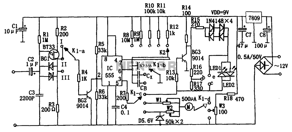
The frequency detection circuit utilizes a transistor line, adjustable via a preset switch K1, to convert capacitance and frequency measurements. The K1 switch is positioned to detect capacitance. The circuit comprises components including a 555 timer, resistors R8 to...
The metal detector circuit includes a fixed frequency oscillator, mixer, detector, detection oscillator, and power amplifier circuit. The fixed frequency oscillator circuit is composed of a ceramic filter (ZC), transistor (V1), resistors (R1 to R4), capacitor (C2), and other...
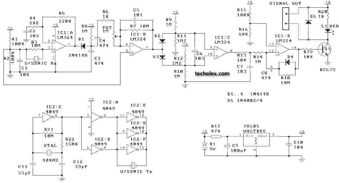
This ultrasonic movement detector circuit utilizes a crystal-locked circuit to achieve maximum performance from the ultrasonic transmitter. The detection circuit is designed to be more sensitive. It is advisable to verify all components against the parts list. Generally, it...
This circuit utilizes the principle of capacitance between two plates to detect when multiple sheets of paper are placed between the sensing electrodes simultaneously. CI is the sensing capacitor, composed of two plates measuring 2 inches by 15 inches...
The Passive Aircraft Receiver is an amplified "crystal radio" intended for receiving nearby AM aircraft transmissions. Its "passive" design does not incorporate oscillators or other RF circuitry that could interfere with aircraft communications, making it suitable for use within...
The PC Standby Detector is a compact circuit designed to deactivate the power LED when the PC enters standby mode. The PC Standby Detector circuit functions by monitoring the power state of the computer. When the computer is in standby...