
Air-Pressure Change Detector
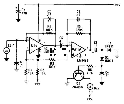
The circuit operates by employing a piezoelectric detector, designated as BZ1, which is sensitive to changes in air pressure. When air pressure varies, BZ1 generates a corresponding voltage signal. This signal is then fed into an operational amplifier configuration, specifically U1A and U1B, where it is amplified to a suitable level for further processing. The design ensures that the frequency response is limited to low frequencies, which is ideal for applications where only slow variations in pressure need to be detected.
The amplified signal is subsequently routed to a rectification stage consisting of diodes D1 and D2. This rectification process converts the alternating current (AC) voltage signal generated by BZ1 into a direct current (DC) signal, making it suitable for driving the next stage of the circuit.
The rectified signal is then used to control a transistor, Q1, which acts as a switch. When the signal from the rectification stage exceeds a certain threshold, Q1 is activated, allowing current to flow to BZ2, the piezoelectric buzzer. BZ2 produces an audible sound as a response to the detected changes in air pressure, alerting the user to the event.
This circuit is particularly useful in applications such as pressure sensing in HVAC systems, environmental monitoring, or as an alert mechanism in various industrial processes. The combination of a piezoelectric detector and a buzzer provides a compact and efficient solution for pressure detection and alerting. A piezoelectric detector (BZ1) is used in this circuit to detect a change in air pressure. BZ1 produces a volt age that is amplified by U1A and UXB. Frequency response is limited to low frequencies. The signal is rectified by D1 and D2 and drives Ql, which activates BZ2, a piezoelectric buzzer. 🔗 External reference
Related Circuits
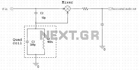
Quadrature FM detectors use a high-reactance capacitor (C2) to produce two signals with a 90 degree phase difference. The phase-shifted signal is then applied to an LC-tuned resonant at the carrier frequency (L1 and C3). Frequency changes will then...
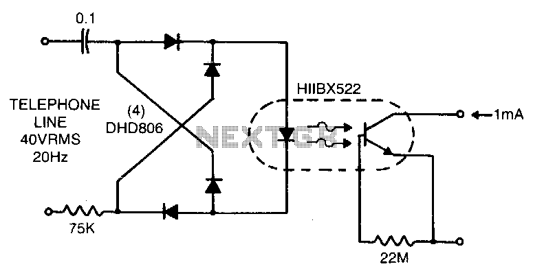
Low line current loading is provided by the H11BX522 photodarlington optocoupler, which delivers a 1 mA output from a 0.5 mA input. The H11BX522 is a photodarlington optocoupler that is designed to provide electrical isolation between its input and output...

I have found this circuit to have better sensitivity, both in distance to a visible bat and in audio frequency, than some other published circuits using a 40kHz transducer with 4000x gain amplification, though the 40kHz transducer I used...
This electronic schematic allows for the design of a simple cellular phone detector circuit capable of sensing the presence of an activated mobile phone from a distance of 1.5 meters. The capacitor C3 should have lead lengths of 18...

The circuit employs a widely used Sharp IR module (the Vishay module may also be utilized). The pin numbers indicated in the circuit pertain to both the Sharp and Vishay modules. For other modules, it is recommended to consult...
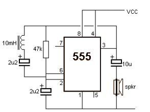
This metal detector electronic project schematic circuit is designed using a simple 555 timer integrated circuit. The schematic circuit requires few external electronic components. The metal detector circuit utilizes the 555 timer IC in an astable mode configuration, which generates...