
cellular phone detector circuit schematic
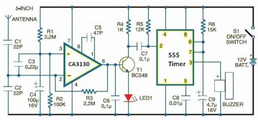
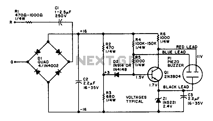
The cellular phone detector circuit operates by utilizing a capacitor configured as a loop antenna, which is sensitive to the radio frequency (RF) emissions generated by mobile phones during active communication. The design emphasizes the importance of the capacitor C3, which must be carefully constructed to optimize its performance at gigahertz frequencies. The specified lead lengths and spacing are critical for tuning the antenna to the correct frequency range, ensuring effective reception of RF signals.
In addition to C3, the schematic likely includes other components such as resistors, diodes, and possibly an operational amplifier to process the detected signals. The circuit may also incorporate a visual indicator, such as an LED, to provide a clear indication of the presence of a mobile phone. The overall design is compact and efficient, making it suitable for applications where monitoring the presence of mobile phones is necessary, such as in secure areas or during examinations.
To enhance performance, considerations such as the orientation of the loop antenna, the surrounding environment, and potential interference from other electronic devices should be taken into account. Proper shielding and grounding techniques may also be implemented to minimize noise and improve detection accuracy. This circuit serves as an educational example of RF detection principles and can be further modified for advanced applications in telecommunications and security systems.Using this electronic schematic, can be designed a very simple cellular phone detector circuit which can sense the presence of an activated mobile cell phone from a distance of one and-a-half meters. The C3 capacitor must have leads length of 18 mm with 8 mm spacing between leads to obtain the desired frequency.
This small disk capacitor acts as a small gigahertz loop antenna to collect the RF signals. 🔗 External reference
Related Circuits
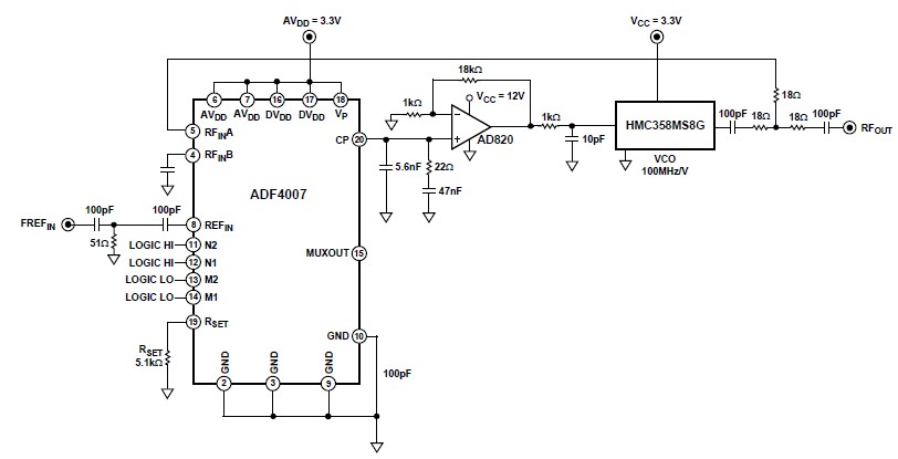
The ADF4007 high-frequency divider Phase-Locked Loop (PLL) synthesizer can be utilized in a variety of communication applications. It operates up to 7.5 GHz on the RF side and 120 MHz at the Phase Frequency Detector (PFD). The device includes...
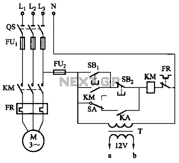
The circuit illustrated in Figure 3-81 employs a transistor delay circuit to facilitate start-stop cycle control. It can operate in both manual and automatic modes. The circuit is primarily governed by the motor run time circuit, which includes transistors...
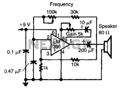
An LM386 audio power IC is configured as a feedback oscillator. It can operate with a supply voltage ranging from 6 to 12 V. The circuit is capable of driving a loudspeaker. The LM386 is a low-voltage audio power amplifier...
The electronic bell operates without a power supply. Most resistors in the circuit are not critical, although capacitor C2 and resistors R2 and R3 perform optimally at the specified values. Omitting resistor R1 will increase the volume of the...
Here a simple design for an attractive tone. They operate on a passive principle, ie without amplification. The circuit only weakened and therefore require no power. As can be seen, the circuit is built with two T-filters in the...
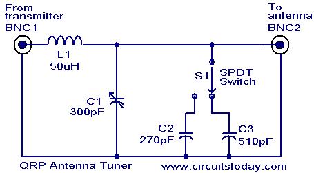
Low power (3 to 30 MHz) transmitters constructed by amateur radio operators are commonly referred to as QRP transmitters. A well-tuned antenna is essential for these transmitters; if the impedance is not properly matched, the output will be minimal...
Warning: include(partials/cookie-banner.php): Failed to open stream: Permission denied in /var/www/html/nextgr/view-circuit.php on line 713
Warning: include(): Failed opening 'partials/cookie-banner.php' for inclusion (include_path='.:/usr/share/php') in /var/www/html/nextgr/view-circuit.php on line 713