
SOLAR BATTERY CHARGER CIRCUIT WITH OVER CHARGE PROTECTION
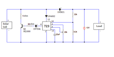
The solar battery charging circuit with overcharge protection is designed to harness solar energy efficiently while ensuring the longevity of the battery. The solar panel, composed of multiple solar cells, converts sunlight into DC electrical energy. The output voltage from the solar panel is variable, depending on the intensity of sunlight. This voltage is directed towards the battery for charging.
The LM723 voltage regulator plays a crucial role in this circuit. It is configured to monitor the voltage level of the battery. When the battery voltage reaches a predetermined threshold, indicating that it is fully charged, the LM723 activates. This action turns on the MJ1000 NPN transistor, which effectively shorts the solar panel's output to ground. By doing this, the circuit prevents any further charging of the battery, thus protecting it from potential overcharge damage.
In addition to the LM723 and MJ1000, the circuit may include supporting components such as diodes to prevent reverse current flow, capacitors for filtering, and resistors for setting the reference voltage for the LM723. The overall design ensures that the solar panel can continuously charge the battery under optimal conditions while safeguarding it from overvoltage scenarios.
The implementation of this solar battery charging circuit is ideal for applications where renewable energy is required, such as in remote locations or for powering small devices. Its reliability and simplicity make it a valuable solution for sustainable energy management.The ultimate source of energy is Sun. it is possible to generate current from sunlight using solar panels. These panels convert light energy into electrical energy. A solar panel consisting of a number of solar cells, which will produce a small amount of current but a bunch of solar cells may contribute enough energy to power a house hold item. Here we are discussing about SOLAR BATTERY CHARGING CIRCUIT WITH OVERCHARGE PROTECTION. The voltage from solar panel will charge the battery to its maximum level. So there is a possibility of damaging the battery (Load) due to overcharging. In order to avoid this we have to introduce a Voltage Regulator using LM723 IC. The voltage regulator triggers whenever the voltage goes above a predetermined value and it enables the NPN transistor (MJ1000) thus the voltage from the solar panel is being grounded and no charge flows to the load. 🔗 External reference
Related Circuits
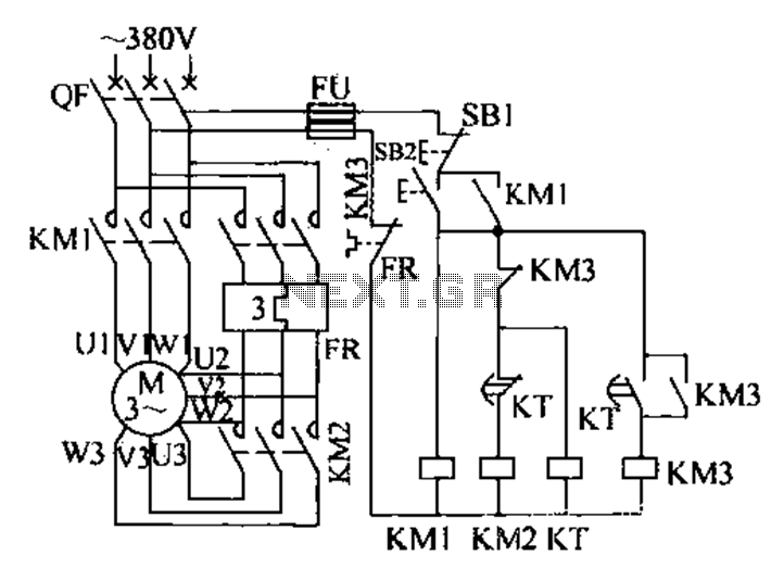
The extended delta decompression starter is designed to manage the operation of a three-phase motor during startup. It involves the initial connection of the motor's three-phase winding set to facilitate a reduced voltage startup, which is achieved through a...
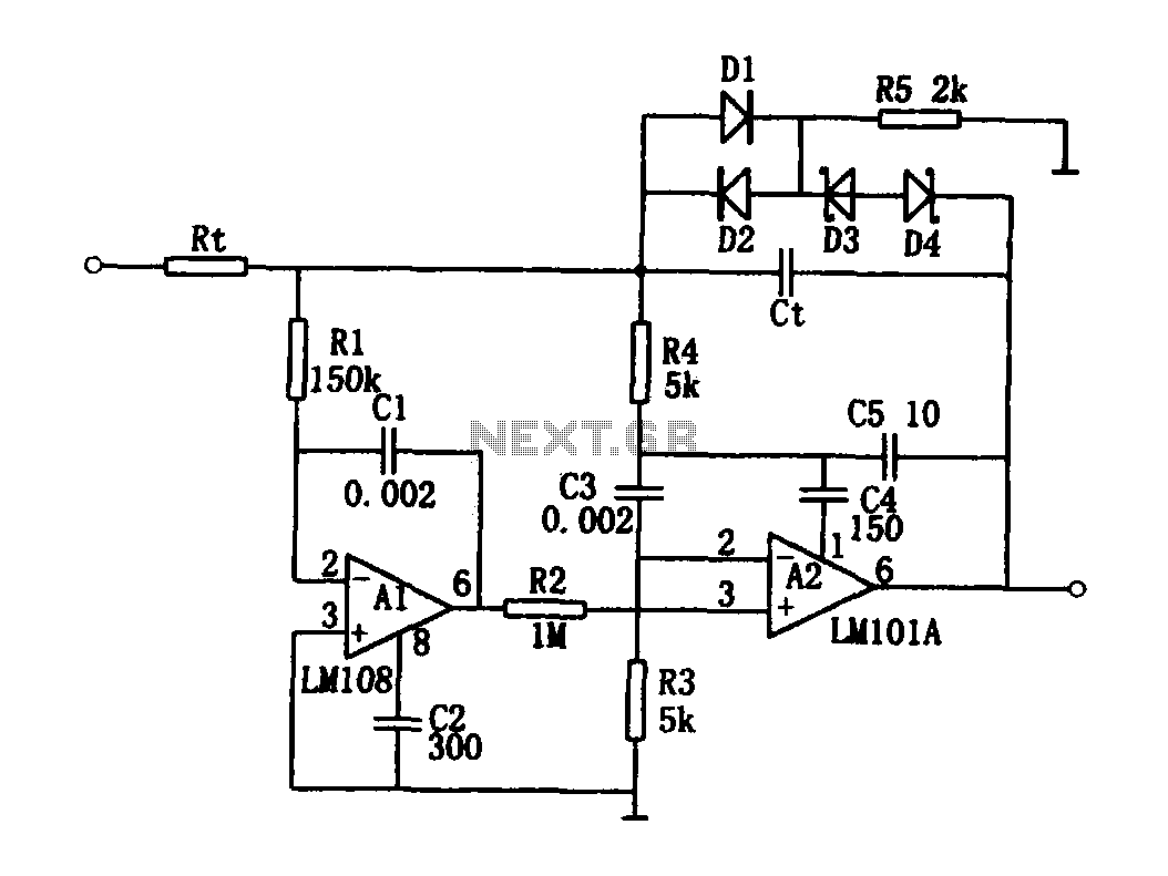
The high-speed integrating circuit is designed with an integration time constant circuit, RtCt, which offers a wide range. When the integrating capacitor Ct is not considered, A2 functions as a positive feedback compensation broadband AC amplifier. The negative feedback...
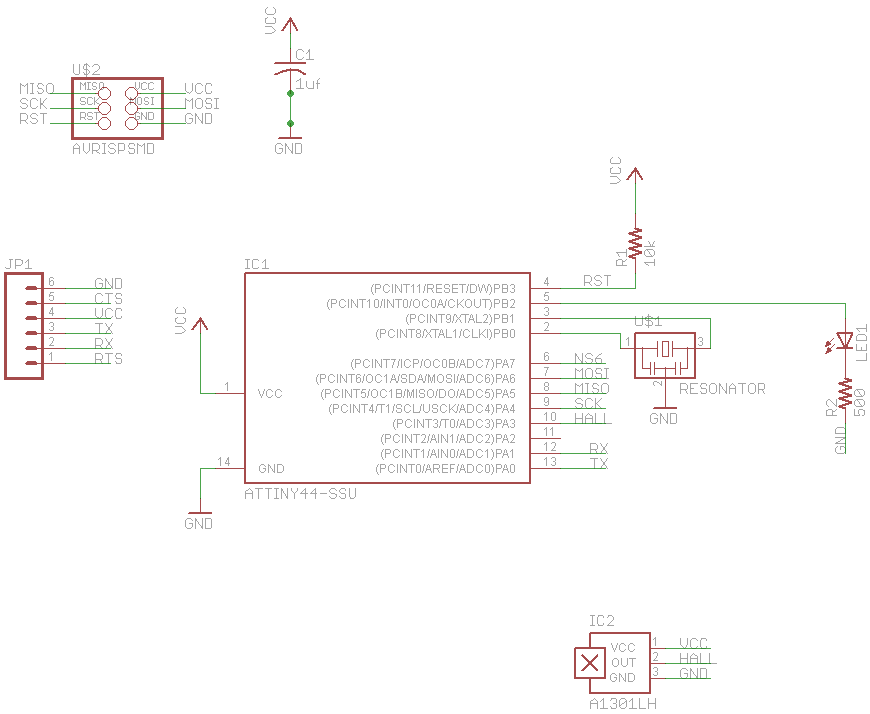
The final project involves cycling rollers that require a method to sense the rotational speed of one of the rollers. Speed sensors on bicycles typically function by detecting a magnet attached to a spoke on one of the wheels...
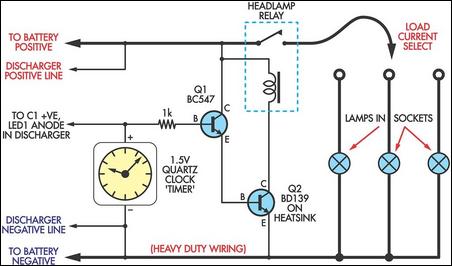
For several years, a rear fog lamp has been mandatory for trailers and caravans to improve visibility in foggy conditions. When this fog lamp is activated, the fog lamp of the towing vehicle must be turned off to prevent...
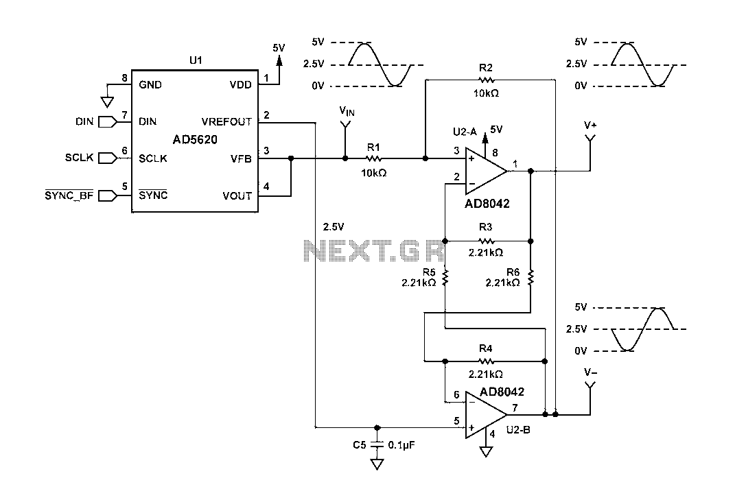
Figure 1 illustrates a circuit that utilizes a single +V power supply and a voltage output Digital-to-Analog Converter (DAC) known as the AD5620. The DAC is controlled via an SPI port, with its output ranging from 0 V to...
If you have a diverse assortment of 12V batteries in different conditions, this straightforward circuit will enable you to easily assess their capacity. This circuit is designed to evaluate the capacity of 12V batteries, which may be in varying...