
ALL band reciever using MC3362
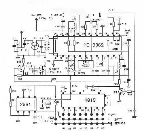
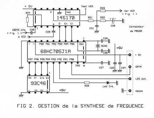
Fig. 2 contains the section manager logic frequency synthesis, the latter being directly provided by a dedicated circuit of a 145,170 MOTOROLA, operation remarkable. The 145,170 receives two pieces of information: - The frequency reference, on pin 1. He is the 10,245 kHz generated by 3362 (Fig. 1). This signal 2049 is divided by a cascade of dividers R. We get the 5 kHz / REF. - The frequency of the VCO produced by MC3362 (n / VCO) injected into the stud 4. This frequency is divided by 12,310 in the case of the receipt of 72,250, the normal direction, giving 61550/12310 = 5 kHz / VCO. N dividers ensuring this mission are scheduled to 12310 to switch on the receiver. 5 kHz both REF and VCO are compared constantly. Any difference is sent by the stud 13 by suitable correction voltage varicap of MC3362. (5000 corrections per second) Under these conditions the frequency of the VCO is locked to the reference frequency and has the stability and accuracy. All channels of a band are obtained with mathematical precision, which is far from being the case when switching on a receiver traditional quartz. Attention quartz 10,245 kHz as a reference, must not be arbitrary. Indeed, when we synthesize the 61550 kHz, any drift of the quartz is found in the 61,550 multiplied by 61550/10245 or by about 6. So you need a very stable temperature quartz. Useful data: the "2049" and "12310" from our example is injected by powering the microcontroller 68HC705J2 MOTOROLA which is responsible for this mission after reading these values in the EEPROM 93Cx6. His work (in less than 50 ms!) 705J2 enters the STOP mode, all the exits blocked and stopped internal oscillator (800 kHz resonator) Under these conditions, the uC does not generate any RF noise and spurious RX21 is also clean "that's equivalent to quartz. When placed under tension, 705J1 begins by reading the entry level of AP2 (DATA). If this entry is 0 (Nothing plugged into the connector PROGR) things happen as stated above. If this entry is 1 (SUPERTEF or programming module connected) does not send anything to the 705J2 145,170 but expects the new data: The lines PA0 PA3 and go to 1, fulfilling this expectation. When receiving 705J1: - He ranks first in RAM (memory) - The data being sent in duplicate, it checks the equality of the two "packages". - If it's good 93Cx6 the program, otherwise ERROR - After that, he reads this 93Cx6 and verifies that the data are checked very well equal the received data (RAM) - If so, the lines PA0 PA3 and fall to 0, ERROR otherwise. If it's good, then you must switch off the RX21, disconnect the controller and restore power to operate on the new frequency. ERROR if the lines remain at 1. We must start the process, but rest assured .... it never happens!
The RX21 is a versatile and advanced receiver designed to address the limitations associated with traditional quartz receivers. It offers a wide frequency access range in 5 kHz steps, allowing for flexibility in various applications. The architecture employs the MC3362 integrated circuit, which plays a critical role in frequency conversion and demodulation processes. The initial signal from the antenna is amplified and filtered before being processed by the MC3362, where it undergoes a frequency shift to an intermediate frequency (IF) of 10.7 MHz, followed by a second conversion to 455 kHz.
The use of a logarithmic amplifier enhances signal handling capability, providing automatic gain control (AGC) that adjusts the gain based on signal strength, thus preventing saturation from strong signals. The output audio signal is generated through a comparator that converts the analog signal into digital square pulses, which are then decoded by a shift register for further processing.
The frequency synthesis section, managed by the 145,170 circuit, ensures that the VCO frequency remains stable and accurate by constantly comparing it to a reference frequency derived from the MC3362. This feedback loop allows for precise tuning across the entire frequency range, mitigating issues related to drift that can occur with standard quartz references.
The microcontroller 68HC705J2 oversees the programming and operational integrity of the RX21. It reads configuration data and manages the receiver's operational state, ensuring that it is capable of adapting to various programming methods, including direct cable and infrared communication. This flexibility is particularly advantageous in applications where the receiver is housed in inaccessible locations, such as waterproof compartments in boats.
Overall, the RX21 represents a significant advancement in receiver technology, integrating sophisticated signal processing and frequency synthesis capabilities to deliver reliable performance in diverse environments.This receptor is born of our annoyance against the irritating problem of Quartz: With the RX21, completed research of cut crystal for your personal rating, you have with him, access to ALL band frequencies, in steps of 5 kHz ! Desiring to make this universal receiver, it not only gives you the choice of frequency, but also the direction of the PPM modulation.
The programming of the received frequency is software-or using the transmitter SUPERTEF (MIE No. 681) if available, or using a small module programming for those with a PPM transmitter whatever. The information transfer may be by direct cable or infrared link, the latter technique for programming the receiver installed in the cell without opening it, which is nice for a plane, but more useful boat in which the receiver is often in a watertight compartment and not directly accessible. Fig. 1 is the schematic for the HF. The signal received by the antenna is amplified by Q1 and screened by L1 and L2. Injected into an MC3362 MOTOROLA, it undergoes a first change of frequency in a blender with the oscillator, tuned by L3 is synthesized, or to 10700 kHz in the received frequency, or to 10700 kHz above, as the modulation is normal or reversed direction. (Relative to our personal systems). Thus, with a SUPERTEF to receive 72 250 kHz, eg. the oscillator is locked on 72,250 to 10,700 = 61 550 kHz, but with FUTABA or another, it will be on 72,250 + 10,700 = 82,950 kHz.
In both cases, the first IF is 72,250 to 61,550 = 10,700 or 82,950 to 72,250 = 10 700 kHz. We simply note that the increase of the 10700 72250 grown in the first case and the fact decreasing in the second. The 10700 kHz is recovered on the pin 19, filtered by the quartz filter F10.7, reinjected by the stud 17.
It then undergoes a second change to another frequency which the oscillator mixer related issue of 10245 kHz, which gives the second FI: 10,700 to 10,245 = 455 kHz which is collected at 5, filtered through the CFW455 and reinjected by the stud 5 in a logarithmic amplifier with high gain. He was finally sent to a quadrature demodulator given by L4. The AF signal modulation is obtained in 13. (Approx. 750 mVpp) The logarithmic amplifier delivers over 10 a current proportional to the amplitude of the signal, so the collected field (0.1 microA per dB) This current is amplified by T2 and T3, the latter controlling the drain voltage of T1, so his gain: With strong field, this voltage drops to 0 and T1 10 dB.
With a weak field, the tension rises to +5 V and T1 10 dB. AGC is a dynamic of 20 dB (range 1 to 100) This prevents the RX21 to be saturated by very strong signals by creating intermodulation noise carriers. It is a quality transparent enough for the average user but very valuable in the field. The audio signal coming from 13 is formed by a comparator 14/15. It was released in 15 in square pulses of 5 VDC positive. These pulses provide an 8-channel decoding using a very classical shift register 4015. 2. Fig. 2 contains the section manager logic frequency synthesis, the latter being directly provided by a dedicated circuit of a 145,170 MOTOROLA, operation remarkable.
The 145,170 receives two pieces of information: - The frequency reference, on pin 1. He is the 10,245 kHz generated by 3362 (Fig. 1). This signal 2049 is divided by a cascade of dividers R. We get the 5 kHz / REF. - The frequency of the VCO produced by MC3362 (n / VCO) injected into the stud 4. This frequency is divided by 12,310 in the case of the receipt of 72,250, the normal direction, giving 61550/12310 = 5 kHz / VCO. N dividers ensuring this mission are scheduled to 12310 to switch on the receiver. 5 kHz both REF and VCO are compared constantly. Any difference is sent by the stud 13 by suitable correction voltage varicap of MC3362. (5000 corrections per second) Under these conditions the frequency of the VCO is locked to the reference frequency and has the stability and accuracy.
All channels of a band are obtained with mathematical precision, which is far from being the case when switching on a receiver traditional quartz. Attention quartz 10,245 kHz as a reference, must not be arbitrary. Indeed, when we synthesize the 61550 kHz, any drift of the quartz is found in the 61,550 multiplied by 61550/10245 or by about 6.
So you need a very stable temperature quartz. Useful data: the "2049" and "12310" from our example is injected by powering the microcontroller 68HC705J2 MOTOROLA which is responsible for this mission after reading these values ??in the EEPROM 93Cx6. His work (in less than 50 ms!) 705J2 enters the STOP mode, all the exits blocked and stopped internal oscillator (800 kHz resonator) Under these conditions, the uC does not generate any RF noise and spurious RX21 is also clean "that's equivalent to quartz.
When placed under tension, 705J1 begins by reading the entry level of AP2 (DATA). If this entry is 0 (Nothing plugged into the connector PROGR) things happen as stated above. If this entry is 1 (SUPERTEF or programming module connected) does not send anything to the 705J2 145,170 but expects the new data: The lines PA0 PA3 and go to 1, fulfilling this expectation. When receiving 705J1: - He ranks first in RAM (memory) - The data being sent in duplicate, it checks the equality of the two "packages".
- If it's good 93Cx6 the program, otherwise ERROR - After that, he reads this 93Cx6 and verifies that the data are checked very well equal the received data (RAM) - If so, the lines PA0 PA3 and fall to 0, ERROR otherwise. If it's good, then you must switch off the RX21, disconnect the controller and restore power to operate on the new frequency.
ERROR if the lines remain at 1. We must start the process, but rest assured .... it never happens! 🔗 External reference
Related Circuits
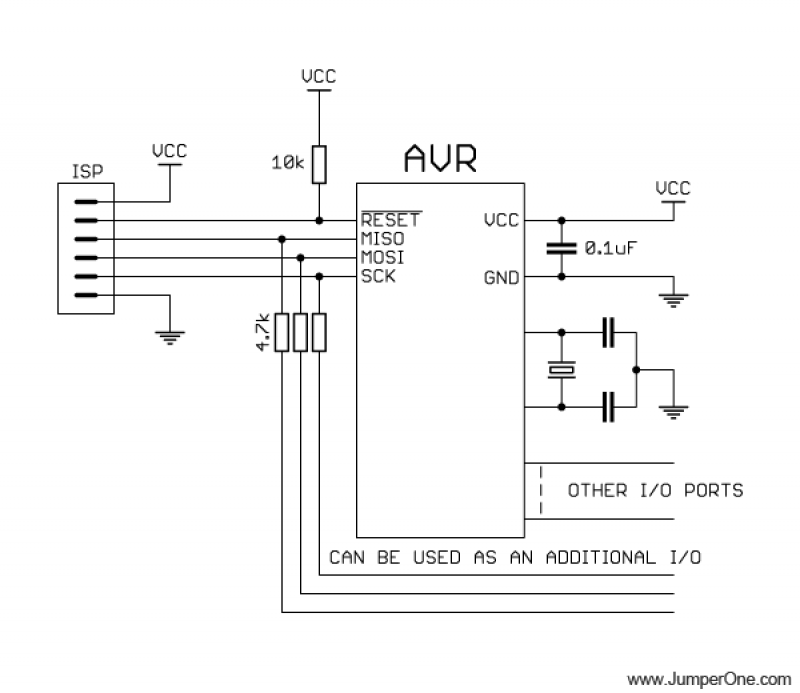
This schematic illustrates the placement of a decoupling capacitor on the right side, which should be positioned as close as possible to the power pins of the microcontroller. It includes a crystal oscillator, which is optional; an internal RC...
A NIXIE tube was mounted on a wooden cigar box, with the anode connected through a large series resistor to the live wire of a 220V mains supply. Touching one of the cathodes caused the numbers to glow, sparking...
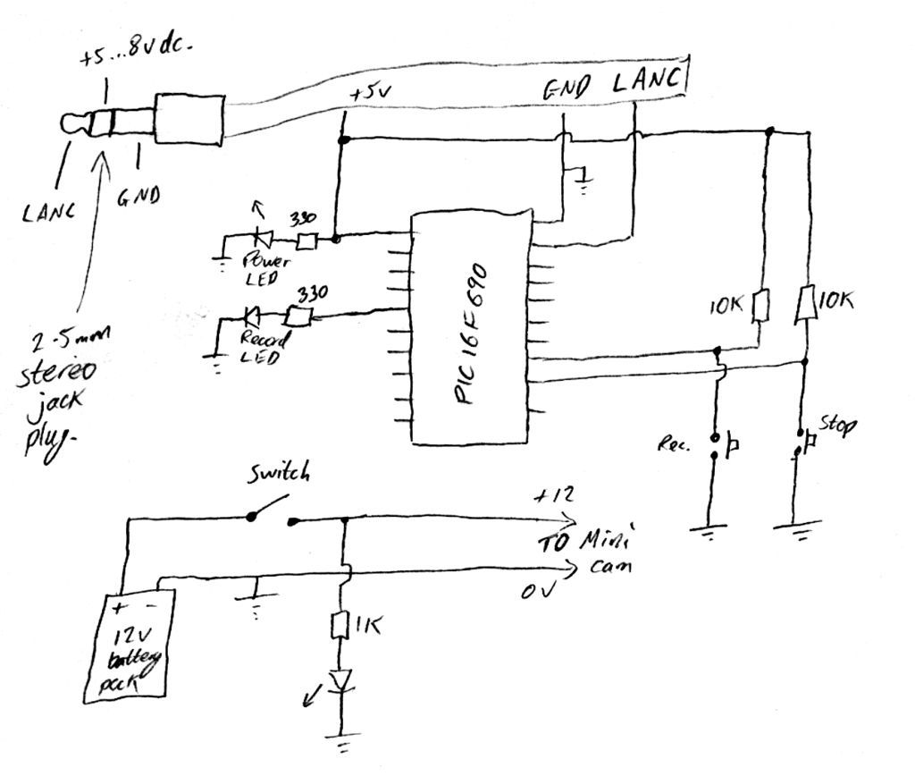
Inexpensive PIC-controlled helmet camera utilizing Sony LANC, suitable for extreme sports. This guide will demonstrate how to create an affordable helmet camera. The proposed electronic schematic involves a PIC microcontroller interfaced with a Sony LANC (Local Application Control Bus) to...
The circuit flashes an LED when detecting an incoming call and is powered by a single 1.5V cell. It is designed to detect incoming calls in a cellular phone. This circuit utilizes a simple yet effective approach to alert users...
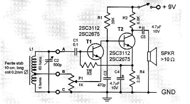
This is a compact and straightforward FM radio receiver capable of tuning into local FM stations. Its minimalistic design renders it suitable for various applications. The FM radio receiver circuit typically consists of several key components that work together to...
Free-space optical (FSO) communication utilizes light as a medium for data transmission. Communication was established between two computers using a laser, independent of any conventional communication methods. Text messages were sent from one PC to another using a system...
Warning: include(partials/cookie-banner.php): Failed to open stream: Permission denied in /var/www/html/nextgr/view-circuit.php on line 713
Warning: include(): Failed opening 'partials/cookie-banner.php' for inclusion (include_path='.:/usr/share/php') in /var/www/html/nextgr/view-circuit.php on line 713