
Solid State Relay Required Only 50uA Drive Current
The described circuit is designed to operate efficiently in environments where minimizing control current is critical, such as in battery-operated devices. The use of a high-current TRIAC allows for the handling of significant power loads, while the sensitive low-current SCR ensures that the control requirements are minimal. This combination not only enhances the efficiency of the circuit but also extends the life of the power source, making it ideal for applications where energy conservation is paramount.
The circuit achieves full isolation, which is essential in protecting sensitive components from voltage spikes and transients that may occur in the load circuit. The transient protection feature is vital for safeguarding against potential damage caused by sudden changes in current or voltage, which can be common in inductive loads.
In practical applications, this circuit can be employed in various scenarios, including remote control systems, automation in industrial settings, or any application where reliable power control is necessary without compromising on safety or efficiency. The design should incorporate appropriate heat dissipation mechanisms for the TRIAC and SCR to ensure stable operation under high load conditions. Additionally, careful consideration of component ratings and circuit layout will further enhance the reliability and performance of the overall system.This circuit demands a control current that is 100 times smaller than that needed by a typical optically isolated solid state relays. It is ideal for battery-powered systems. Using a combination of a high current TRIAC and a very sensitive low current SCR, the circuit can control about 600 watts of power to load while providing full isolation and
transient protection. 🔗 External reference
Related Circuits
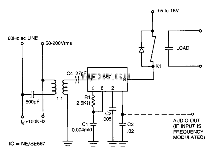
Carrier current remote control device or intercom circuit diagram as follows: The circuit diagram for a carrier current remote control device or intercom system typically involves the use of carrier current technology to transmit audio signals over existing electrical...

This is a 1-amp variable-voltage power supply unit (PSU) that can adjust output voltage from approximately 3V to 24V. It features a maximum output current limit, which is particularly useful when powering up a project for the first time...
Volt regulators such as the LM708 and LM317 series sometimes need to provide a little bit more current than they actually can handle. If that is the case, this little circuit can help out. A power transistor such as...
The current source in the diagram reacts very quickly to changes in the input signal and may be utilized in specific measurements. The differential amplifier IC1 ensures that the voltage across resistor R2 is equal to the input voltage,...
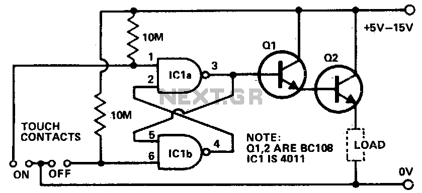
Touching the on contacts with a finger brings pin 3 high, turning on the Darlington pair and supplying power to the load (transistor radio, etc.). Q1 must be a high-gain transistor, and Q2 is chosen for the current required...
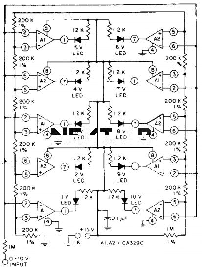
The circuit utilizes CA3290 BiMOS dual voltage comparators. The non-inverting inputs of A1 and A2 are connected to a voltage divider reference. The input signal is applied to the inverting inputs. LEDs are activated when the input voltage reaches...