
Alternative Halogen Power Supply
The described circuit provides a practical solution for powering halogen lamps using an existing PC power supply without the need for modifications. This design leverages the 5V and 12V rails of the power supply, ensuring a smooth transition from initial heating to stable operation. The use of two operational amplifiers (IC1.A and IC1.B) plays a critical role in controlling the timing and switching of the transistors (T1 and T2), which manage the power delivery to the halogen lamp (LA1).
The initial connection to the 5V rail allows for a quick warm-up period, while the subsequent switch to the 12V rail ensures that the halogen lamp operates efficiently without drawing excessive current that could trip the power supply's protection mechanisms. The inclusion of diodes (D1 and D2) provides necessary protection against voltage spikes and over-voltage conditions, enhancing the reliability of the circuit.
Resistors R4 and R5 are essential for controlling the base current to the transistors, allowing for stable operation and preventing potential damage to the components. The quenching diodes (D3 and D4) further protect the circuit from back EMF generated by the inductive loads when the transistors switch off.
The adjustable timing feature provided by potentiometer P1 offers flexibility in the warm-up time of the lamp, accommodating various types of power supplies and user preferences. This adaptability is beneficial for achieving optimal performance across different setups, making the circuit a versatile choice for users looking to utilize halogen lamps in conjunction with standard PC power supplies. Overall, this design exemplifies efficient engineering practices in circuit design, ensuring functionality, safety, and user customization.Readers who do not care to modify the power supply of an old PC into a suitable halogen power source (see our April 2006 issue), may find the present design a welcome alternative. The circuit does not need any changes to the power supply. It allows the halogen lamps to be initially powered from the 5V rail of the supply via RE2, so that they are p
reheated. Subsequently, they are powered from the 12-V rail via RE1, while at the same time the 5-V rail is disconnected. This ensures that the current surge through the lamps is so small that the protection in the power supply does not react.
Operation of the circuit is as follows. As soon as the PC supply provides power, IC1. B drives T1 into conduction and RE2 closes. The potential at the non-inverting input of IC1. B is 6 V, while that at the inverting input rises from 0 V. Lamp LA1 is then connected to the 5-V rail. After a short span of time, the voltage across C1 has risen to a value where IC1. B changes over, whereupon T1 is cut off. At the same time, IC1. A drives T2 into conduction. The circuit is then decoupled from the 5-V rail and connected to the 12-V terminal. The 5-V rail in the PC power supply is protected against spikes on the 12-V line by D1. Diode D2 protects IC1 against over-voltage on its inputs should the 12-V rail fail. Resistors R4 and R5 limit the base currents of the transistors. D3 and D4 are quenching diodes. The time during which lamp LA1 is powered by 5 V is preset with potentiometer P1. The maximum time span is about 0. 33 s and the minimum 3. 3 ms. The latter is perhaps rather short, but it also depends to some extent on the type of power supply used. Some experimentation may be worthwhile! 🔗 External reference
Related Circuits
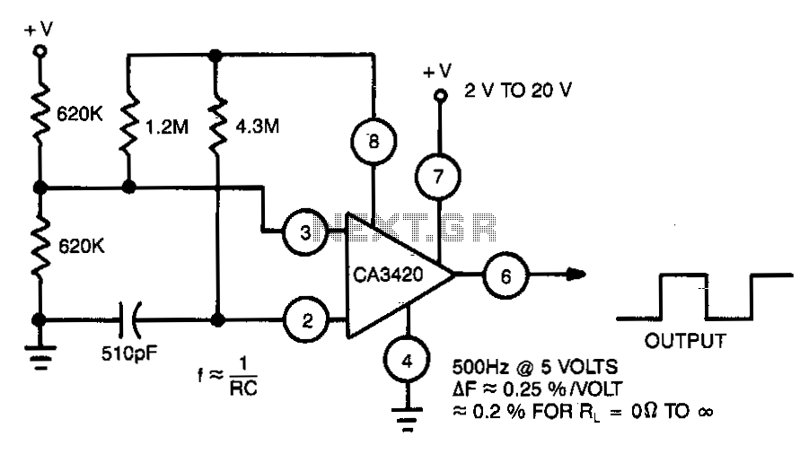
This multivibrator utilizes a CA3420 BiMOS operational amplifier to enhance frequency stability. The output frequency remains largely unaffected by supply voltage variations. Due to the inherent buffering action of pin 6, the frequency shift is approximately 0.2% when the...
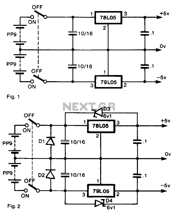
To generate regulated ±5-V supplies from a pair of dry batteries, the circuit shown in Fig. 1 is commonly utilized. To protect against inadvertent reverse connection of a battery, a diode in series with each battery would create an...
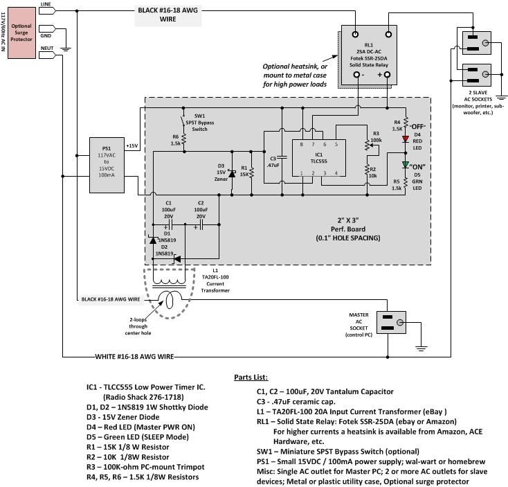
Most Apple and Windows PCs can enter "sleep" or "standby" mode when not in use instead of being completely shut down. This mode allows the operating system to restore all previous work sessions within seconds upon waking via keyboard...

Position L near the transmitter output tank to hear the key-down tone. Then secure the coil in place. C = 47 µF, R = 8 kΩ, Q = HEP 253 (or equivalent), T = 500: 500 ohm center-tapped transformer....
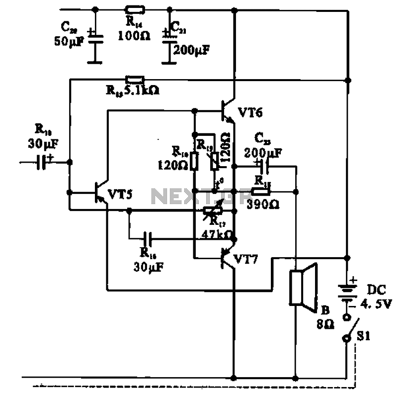
The transistor radio features a common output transformerless (OTL) power amplifier circuit. The VT5 component serves as the bias resistor for the driver stage. VT6 and VT7 form a complementary symmetry configuration, with VT6 being a germanium NPN transistor...
In this circuit, the 7815 regulates the positive supply, and the 7915 regulates the negative supply. The transformer should have a primary rating of 240/220 volts for Europe, or 120 volts for North America. The centre tapped secondary coil...