
Q-Multiplying Loop Antenna
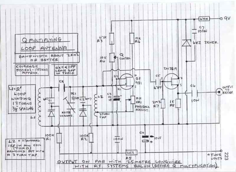
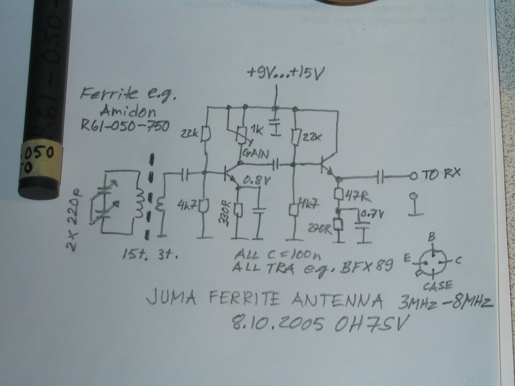
The circuit described is intended for use with a 4-foot square loop antenna, which is a common choice for medium wave (MW) radio reception, particularly in applications requiring long-distance signal capture. The loop antenna operates on the principle of electromagnetic induction, where the loop's dimensions are optimized to resonate at medium wave frequencies, typically ranging from 530 kHz to 1700 kHz.
The schematic likely includes components such as a tuning capacitor to adjust the resonant frequency of the loop, a matching transformer to efficiently couple the antenna to the receiver, and possibly an amplifier stage to boost weak signals. The tuning capacitor allows for fine adjustments to be made to the loop's resonant frequency, ensuring optimal reception of desired signals while minimizing interference from other sources.
Additionally, the circuit may incorporate a low-noise amplifier (LNA) to improve the signal-to-noise ratio, which is crucial for long-distance reception. The LNA should be designed to operate within the frequency range of interest and be placed as close to the antenna as possible to reduce losses.
Power supply considerations must also be addressed, ensuring that any active components receive a stable voltage without introducing noise into the system. Bypass capacitors may be included to filter out high-frequency noise from the power supply.
Overall, the design aims to maximize the effectiveness of the 4-foot square loop antenna in capturing distant medium wave signals while minimizing noise and interference, resulting in clearer audio output for the end-user.This circuit is designed to be used in conjunction with the standard 4 foot square loop used in MW for long distance reception. 🔗 External reference
Related Circuits
A few months ago, I decided to build a compact, yet effective alarm. My demands were: simple construction, reliable operation, very small power consumption, and, most of all, small size. I started with CMOS logic gates, but was soon...
The antenna used for receiving or transmitting is a crucial component in a communication link. Its performance significantly influences the effectiveness of both the receiver and transmitter. Antennas are reciprocal, meaning an antenna designed for transmission can also function...
Described here is a simple omnidirectional, vertically-polarised dipole for two metres. Made from coaxial cable, it can be rolled up and stored in a small container. It may be used as is indoors, or waterproofed for use outside. No...
Antennas that are much shorter than 1/4 wavelength present a very small and highly relative impedance that is dependent on the received frequency. It is difficult to match impedances over a decade of frequency coverage. Instead, input stage Q1...
The red connector is designated for an optional external antenna wire, while the black connector serves as the ground wire. The red wire is connected to the secondary winding, and the black wire is linked to the circuit ground...
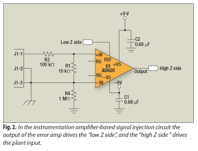
A signal-injection circuit for control-loop analysis is flat from DC to 200 kHz, isolated from chassis ground, and easily constructed with a readily available instrumentation amplifier. The signal-injection circuit is designed to facilitate control-loop analysis by providing a stable and...