
AM Radio
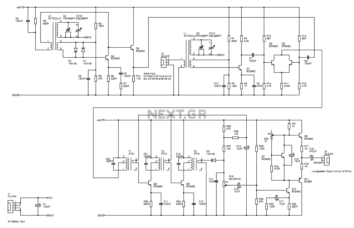
The MW AM radio circuit described utilizes a combination of transistors, diodes, and passive components to create a functional AM receiver. The core of the design relies on the BC549 transistors, with the option of using the BC559 in the audio output stage, providing a straightforward yet effective amplification solution for the received signals. The radio is powered by a 9V battery, ensuring sufficient voltage for operation.
The intermediate frequency (IF) transformers, T1, T2, and T3, are custom-wound based on calculations for the desired inductance at 455 kHz, which is a standard IF frequency for AM radios. The inductance values are determined using the formula for resonance, ensuring proper tuning with the associated capacitors. The use of "Al" values for the coil formers allows for precise control over the inductance achieved through the number of turns wound on the transformer cores.
In the signal processing chain, Q4 operates as a class A amplifier, providing gain while the feedback from the collector circuit stabilizes the overall performance. The differential amplifier configuration formed by Q2 and Q3 allows for cancellation of the common-mode signals, focusing on the differential signal that results from variations in current between the two transistors. This configuration enhances the radio's sensitivity to weak signals.
The signal limiting is managed by diodes D1 and D2, which stabilize the amplitude across the frequency range, preventing distortion and ensuring a clean output. The automatic gain control (AGC) feature is achieved through a network involving the demodulating diode D3, volume control R16, and resistors R27 and R29. This network dynamically adjusts the bias current to the IF transistors based on the strength of the received AM signal, ensuring optimal performance across varying signal conditions.
The design also incorporates emitter resistors bypassed by capacitors, maximizing gain at radio frequencies while maintaining stability under low signal conditions. The careful arrangement of components and the use of feedback mechanisms contribute to a robust and functional MW AM radio capable of delivering quality reception and audio output.A MW AM radio like those you buy, or used to buy. Use just BC549 trannies, with the BC559 complement being allowed in the audio output stage. Buying RF antenna coils, oscillator coils and intermediate frequency transformers would be cheating - wind your own. 9V battery powered. The transistor Q4 is biased up as a class A amplifier with some gain. The collector circuit provides feedback to the base via the tuned circuit. The two diodes D1 and D2 make a limiter to stabilise the amplitude across the frequency range. This is a differential amplifier comprising Q2 and Q3 with the two collectors connected together instead of going to individual loads to +BAT.
The normal difference voltage output that you'd expect is therefore cancelled and you are left with the much smaller signal which is the effect of more current flowing in one transistor reducing the current flowing in the other, thus reducing its partner's gain and vice-versa. The turns ratios for these home wound Intermediate Frequency Transformers, T1, T2, and T3, were determined by looking up the turns ratios used in TOKO brand transformers for the 1st 2nd and 3rd IFTs. The number of turns for the primaries were first determined by calculating the desired inductance to resonate with the parallel capacitor at the IF of 455kHz.
fo=1/2pi*sqrtLC where C is about 220pF typically. Then using the tables supplied with the coil formers and cores the approximate number of turns can be found using the "Al" values. This value gives you a nominal inductance per 1000 turns, and the inductance is proportional to the square of the number of turns.
So if the quoted Al for a certain former and core is Al=10uH/1000Turns, and if you wanted 5uH you would wind (5^2/10^2)*1000=250 turns. The Al values work pretty well and I didn't need to rewind after testing, though I may have changed the parallel capacitor value for T1.
An RF signal generator was used to check the resonant frequency and to set the cores in about the right positions prior to wiring up. An interesting fact reveals itself in the IF strip. The transistors do not need to be class A biased as you would normally do in a cascaded audio amplifier chain.
Because the inductance of the IFTs stores energy, and we are dealing with an AM signal, you can bias the transistors pretty much in class C, only increasing the bias current when maximum gain is needed on weak signals. The signal at the collectors swings above and below +BAT thus also effectively doubling the possible signal swing range.
This isn't so important for a 9V radio like this one, but there are very good MW radios out there with 3V and even 1.5V batteries where this must be an important design feature. The schematic shows the emitter resistors bypassed with a capacitor to maximise gain at radio frequency, while the 220R stabilises the bias current when it is flowing significantly under low signal conditions.
The bias voltage itself comes from the network comprising the demodulating diode D3, the volume control R16, and R27 and R29. R28 and C15 remove the audio from the d.c. part of the demodulated signal. The network is arranged such that when there is no signal present the full bias voltage is applied to the IF transistors and you get about 2mA quiescent current and a fair gain.
When a strong AM signal comes along it is rectified and the audio tapped off. But the rectified audio is also creates a negative bias which reduces the voltage on the electrolytic cap. The reduced bias voltage puts less bias current through the IF trannies and the gain is reduced. This primitive AGC action is similar to that used in the very old Roberts radios. 🔗 External reference
Related Circuits
A simple radio receiver circuit is illustrated. This receiver is designed to capture signals from amateur radio stations operating in the shortwave (SW) bands of 10, 15, 20, 40, and 80 meters. The direct-conversion receiver comprises a set of...
Superheterodyne receivers have been mass-produced since around 1924, but for reasons of cost did not become successful until the 1930s. Superheterodyne receivers represent a pivotal advancement in radio technology, characterized by their ability to convert high-frequency signals into lower...
Nearly all AM radio manufacturers utilized this specific circuit from approximately 1948 to 1963. There is a growing interest in collecting these radios as antiques. Credit for the creator of this figure and caption is sought, but the source...
Ham Radio (amateur radio) is a popular hobby amongst electronics enthusiasts all over the world. Basically the hobby involves a person in making his own gear consisting of a receiver and transmitter or a transceiver (a receiver and a...

The relay power in the linear circuit is derived from a -120 V bias supply, while the transmit keying output from the Kenwood device is +12 V with a maximum current of 10 mA. A critical component of this...
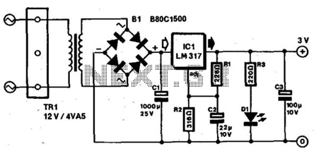
Most small portable radios require a 3-V supply, which is typically provided by two AA or AAA batteries. Many of these radios are equipped with a charger socket since rechargeable batteries are an option. When used in a stationary...