
Amazing All-Band Receiver
The Amazing All-Band Receiver circuit is designed to operate efficiently across a wide range of frequencies, making it a versatile tool for both casual users and advanced experimenters. The use of a Schottky diode ensures minimal signal loss and high sensitivity, allowing for the detection of weak signals that might otherwise go unnoticed. The audio amplifier stage boosts the detected signals to a level suitable for listening through earphones, with careful consideration given to the impedance matching to ensure optimal performance.
The antenna design plays a critical role in the receiver's functionality. The recommended 6-inch length serves as a good starting point, but users can experiment with different lengths to fine-tune the reception for specific frequency bands. The use of an RCA connector facilitates easy antenna swaps, and the option to use loop antennas opens up additional possibilities for signal enhancement, particularly for single frequency applications.
The circuit's low power consumption is a significant advantage, allowing for extended use without frequent battery replacements. This is especially important for portable applications where battery life is a concern. The design's simplicity, combined with its ability to detect a wide variety of signals, makes it an ideal project for electronics enthusiasts looking to explore radio frequency phenomena.
In applications where higher sensitivity is required, the addition of a tuned circuit can further improve performance, particularly for short-wave frequencies. The inclusion of a choke in the antenna line helps to filter out unwanted high-frequency signals, ensuring that the receiver remains focused on the desired AM signals.
Overall, the Amazing All-Band Receiver is a remarkable device that showcases the capabilities of simple electronic components to create a versatile and effective radio receiver. Its design allows for significant customization, enabling users to tailor the device to their specific listening needs and preferences.The Amazing All-Band Receiver is basically a diode detector followed by a high-gain audio amplifier. This is not a multi-band receiver; it picks up everything at once! The detector uses a biased Schottky diode for excellent sensitivity and bandwidth; the detector will detect signals from below the AM broadcast band up to the microwave bands. The n umber of interesting signals is surprising; it is fun to drive around listening to the numerous strange sounds. By trying different antennas and locations, this receiver has picked up AM radio stations, FM stations, TV video (buzz), car lock transmitters, cell phones, and even the microwave oven (a whoosh-whoosh sound as the microwave spreader rotated).
It isn`t clear how FM stations are demodulated; perhaps the antenna Q is sufficient for slope detection. (See reader Karen`s excellent theory. ) Even the familiar buzz from a narrow-band FM pager transmitter has been heard - somehow. There are some mysterious signals out there, too! What is that occasional descending whistle over by the highway Some vehicles emit a curious buzz, too.
If you hear a mysterious click-click now and then, its your cell phone! Don`t expect to tune in international shortwave stations. This receiver is for strong, local sources. The advanced experimenter will find it useful as a detector section for low power tuned receivers. Other signals that should be easy to receive include in-flight aircraft transmissions (this passive receiver will not interfere with communication/navigation systems), CB radio transmissions, amateur transmitters, "bugs", wireless networks and devices, radars, radio control transmitters, certain security/alarm systems, and even unexpected oscillations in your next circuit. A short, perhaps 6", antenna is a great general-purpose length for general listening but trimming the length for the a desired band will give better sensitivity.
For the antenna connection, use an RCA or similar connector with the ground connected to the battery negative in case you want to try a loop antenna. Loop antennas (loose end connected back to ground) work especially well for single frequencies and a tuning capacitor may be added across the loop.
This detector circuit will also work well as a crystal radio, even at higher short-wave frequencies with the addition of a simple tuned circuit. Add a 10 to 100uH choke in series with the antenna near the receiver to keep out the higher frequency signals when listening to AM stations and connect the diode to a fairly high impedance tap on the tuned circuit since the diode impedance is high in this circuit.
The 100pF capacitor and 10k resistor are not needed as long as the tuned circuit provides a DC path to ground for the diode. (See Crystal Radio Circuits for tuned circuit ideas. ) The above schematic shows a 100k volume control but the signals usually aren`t loud so this component may be replaced with an ordinary 100k resistor.
The. 01uF capacitor would connect directly from the collector of the first transistor to the base of the second. This amplifier is non-inverting so a feedback squeal will be heard if the earphone wires are too near the antenna.
Reduce the 100pF in the antenna if feedback squeal is a problem. The circuit draws only about 125uA so battery life is excellent. The circuit is designed for a sensitive crystal earphone and cannot drive most other types of earphones. One notable exception is older sensitive dynamic headphones which are rare treasures. To drive a lower impedance earphone, say a 60 ohm type, lower the last transistor`s collector and base resistors from 100k and 10Meg to 1k and 100k but remember that the battery current will be much higher.
An 8 ohm earphone will require a different output stage for satisfactory performance. An inexpensive plastic box makes a great housing. The unit below employs a couple of pieces of tinned circuit board to hold the circuitry and to act as a 🔗 External reference
Related Circuits
The circuit operates at a voltage of 9V with a current consumption of only 5mA. It allows for frequency adjustment within the range of 150 to 180 kHz, featuring a bandwidth of approximately 20 kHz. This configuration ensures that...
A very simple circuit for an FM receiver that does not require an integrated circuit (IC) and utilizes only a single transistor. The functionality of this transistor is uncertain. This design represents a regenerative or super-regenerative radio receiver. There...
Superheterodyne receivers have been mass-produced since around 1924, but for reasons of cost did not become successful until the 1930s. Superheterodyne receivers represent a pivotal advancement in radio technology, characterized by their ability to convert high-frequency signals into lower...
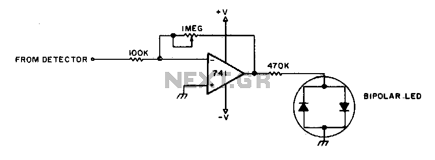
To adjust, tune into a station and adjust the I"M pot for a null. Then ask the station to modulate and fine-tune so modulation peaks do not light the LEDs. Stations are properly tuned when neither LED is lit. The...
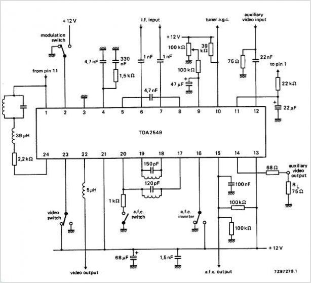
The circuits utilize two FM Demodulator TDA2555 systems to execute the demodulation functions necessary in a dual sound carrier television system for demodulating the sound carriers. The distinction between the TDA2555 and TDA2557 lies in the number of stages...
This receiver, designed around the popular ZN414 integrated circuit, operates within the AM band frequency range of 550 to 1600 KHz. For Longwave reception, it is necessary to replace the coil, which can be sourced from an old medium...