
Zero center indicator for FM receivers
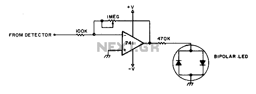
The circuit described involves a tuning mechanism for receiving radio signals, specifically focusing on achieving a null condition for optimal reception. The "I'M pot" refers to an adjustable potentiometer used for fine-tuning the input signal. The process begins by tuning into the desired radio station and adjusting the potentiometer until a null point is reached, where the output signal is minimized or balanced.
Once the null condition is established, the station is requested to modulate. This modulation is likely a test signal that varies in amplitude or frequency to ensure the receiver's response is appropriate. The fine-tuning process is critical; it involves adjusting the potentiometer further to ensure that modulation peaks do not activate the LEDs. The LEDs serve as indicators of signal strength or modulation presence. Therefore, the goal is to achieve a state where neither LED is illuminated, which indicates that the station is properly tuned and the receiver is optimally configured to handle the incoming signal without distortion or overload.
In summary, the tuning procedure is essential for ensuring clear reception of radio signals while avoiding false indications from the LEDs, which would suggest improper tuning or excessive modulation. Proper adjustment of the I"M pot is crucial in achieving this balance, leading to an effective and efficient radio communication system.To adjust, tune in a station and adjust the I"M pot for a null. Then ask the station to modulate and fine adjust so modulation peaks don"t light the LEDs Stations are properly tuned when neither LED is lit. 🔗 External reference
Related Circuits
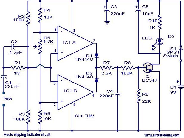
This circuit is designed to detect clipping in a specific waveform. Clipping occurs when the amplitude of a waveform decreases before reaching its expected limit. The circuit activates an LED as an indication that the tested signal is experiencing...

If an amplifier is equipped with two level controls, it provides both a balance control and a level control. A drawback of this configuration is the difficulty in accurately setting the balance. This issue can be resolved by replacing...
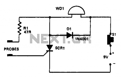
In this circuit, a warning device (WD1) is connected in series with a silicon-controlled rectifier (SCR1). When the liquid level creates a conductive path between the probes, the SCR becomes conductive, activating the warning device. The warning device can...
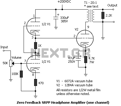
To get a low output impedance I needed to use quite a high step-down ratio (20:1); after all, the amplifier may be used with headphones of lower impedance than the 300 Ohms of the HD600. The output valve is...
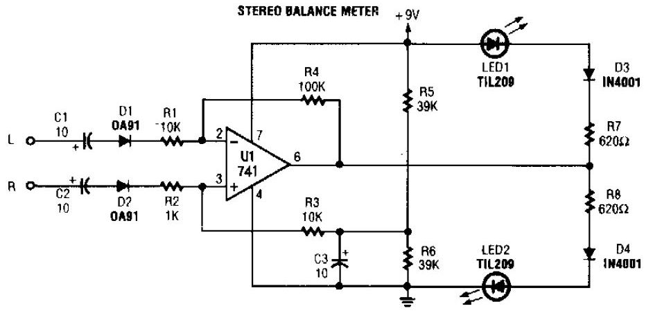
The simplest stereo balance meter circuit schematic available on the internet. When the left and right signals are equal, no output is present from U1 and pin. This stereo balance meter circuit is designed to visually indicate the balance between...

This simple circuit indicates the status of a phone, including Line OK, Dialing, and Call Attended. It also features a locking mechanism to block outgoing calls while allowing incoming calls, preventing misuse of the telephone. The circuit requires only...
Warning: include(partials/cookie-banner.php): Failed to open stream: Permission denied in /var/www/html/nextgr/view-circuit.php on line 713
Warning: include(): Failed opening 'partials/cookie-banner.php' for inclusion (include_path='.:/usr/share/php') in /var/www/html/nextgr/view-circuit.php on line 713