
Ammeter and Precision Rectifier
The current measurement circuit is designed to provide accurate and reliable readings for both DC and AC currents, catering to a wide range of applications in electronic systems. The use of a shunt resistor allows for minimal disruption to the circuit while facilitating the measurement process. The selection of current ranges ensures versatility and adaptability to various measurement needs, making it suitable for both low and high current applications.
In the DC measurement mode, the configuration allows for a straightforward interpretation of current levels, as the DPM directly correlates the measured voltage to the current flowing through the shunt. This method ensures that users can easily assess the power consumption of their circuits, facilitating efficient design and troubleshooting.
For AC measurements, the integration of IC2 as a buffer and IC3 as a precision rectifier enhances the accuracy of the readings. The operational amplifier's role in converting the AC signal into a readable DC equivalent allows for precise current measurements, even in fluctuating conditions. The capacitors C10 and C11 serve to filter the signal, ensuring that noise is minimized, which is crucial for maintaining measurement integrity.
Overall, the circuit is a robust solution for current measurement, providing essential functionality for engineers and technicians in various electronic applications.Studying current measurement is a prerequisite for many of the measuring techniques. The current parameter mainly specifies the power consumption in a circuit, given the value of resistance. It is found convenient to measure current rather than voltage for knowing power output and determining efficiency.
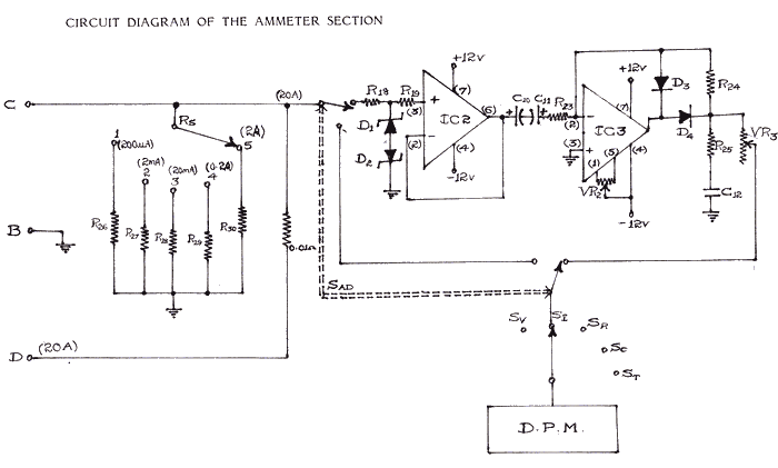
It may be required to measure leakages in c ircuits at certain times. Hence the measurement of current constitutes a priority. The circuit diagram for the measurement of current (d. c. and a. c. modes) is shown aside. For measurement of current switch SI is operated. The switch S-ad is kept in d. c. mode. This enables the current to pass through a shunt circuit consisting of resistors R26, R27, R28, R29 and R 30. The current ranges are provided in 5 decades i. e. 200 micro-amps, 2 milli-amps, 20 milli-amps, 200 milli-amps and 2 amps. An additional current range that can be read upto 20 Amps is also provided. However, for measuring this high current the green terminal provided on the meter should be used. When a current to be measured is fed to the input terminals of the instrument appropriately, a voltage proportional to the current through the shunt resistor is fed into the DPM which measures the d.
c. voltage which in turn indicates the d. c. current being fed. In case of a. c. measurement, the switch S-ad is kept in a. c. mode. The a. c. current path is similar to the d. c. current path in the shunt resistor. However the voltage tapped across the shunt resistor is fed into IC2 which is a buffer. The output of IC2 is fed to IC3 through capacitors C10 and C11. This IC is an operational amplifier acting as a precision rectifier. The output of IC3 is fed to the input of the DPM for measuring the a. c. current being fed to the input terminals. It can be seen that the current measurement is similar to the voltage measurement except that the attenuator chain is replaced by the shunt resistor circuit. We aim to transmit more information by carrying articles. Please send us an E-mail to wanghuali@hqew. net within 15 days if we are involved in the problems of article content, copyright or other problems.
We will delete it soon. 🔗 External reference
Related Circuits
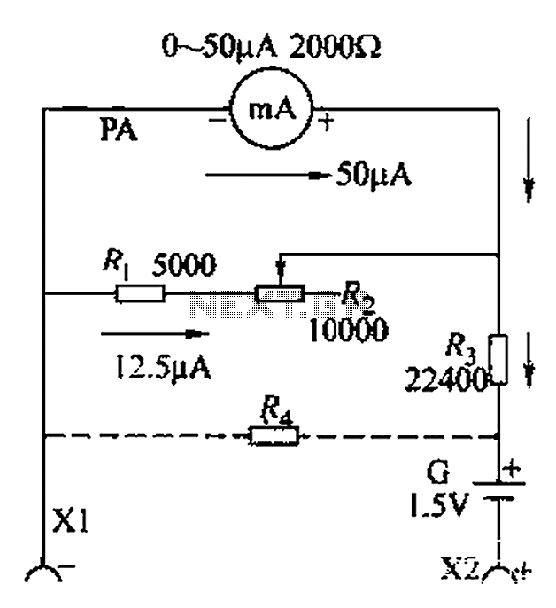
A commonly used high-sensitivity header utilizes a microammeter to create a resistance meter capable of measuring very low voltages. The design adheres to the principles of a milliameter resistance meter. The circuit diagram is illustrated in Figure 5-37, which...
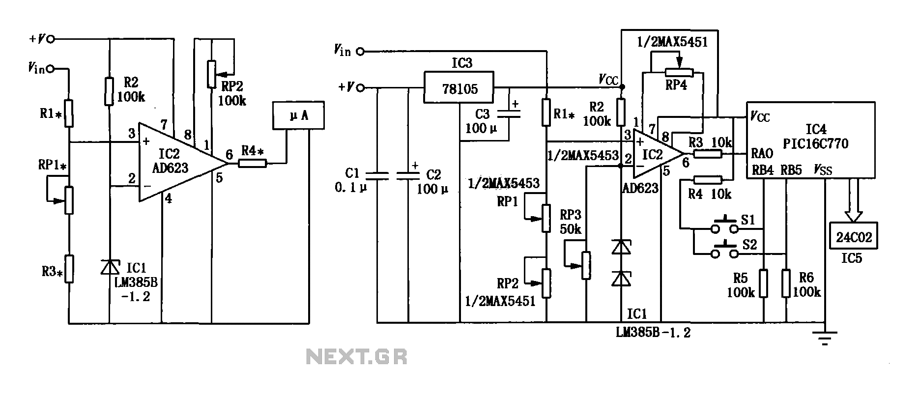
The range precision voltmeter electrical schematic is depicted in Figure (a) below. It features an amplifier circuit and several high-precision components that significantly enhance the performance range of the voltmeter. The inverting input of the instrumentation amplifier AD623 (IC2)...
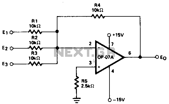
This circuit generates continuous outputs that depend on multiple input variables. The circuit in question typically employs a combination of operational amplifiers (op-amps), resistors, and potentiometers to achieve its functionality. The outputs can be tailored based on the variations...
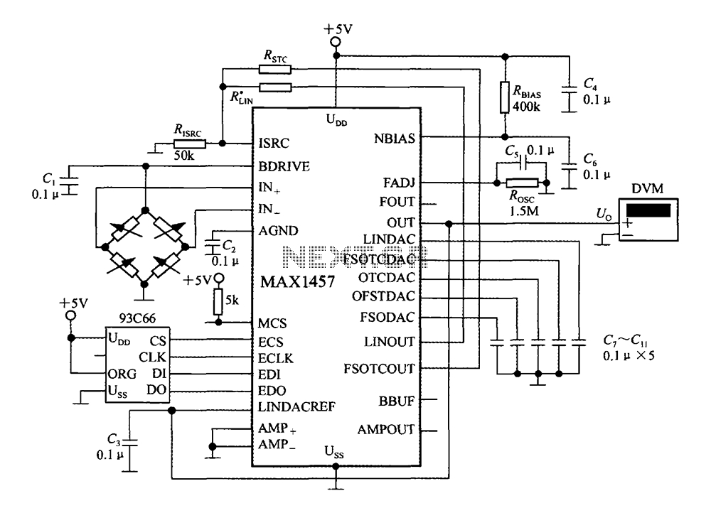
The circuit diagram illustrates a digital precision pressure tester using the MAX1457 integrated circuit with an external ROM selection of the 93C66 type, which is a 4096-bit E2PROM. Upon powering on, the MCS pin is pulled to a high...
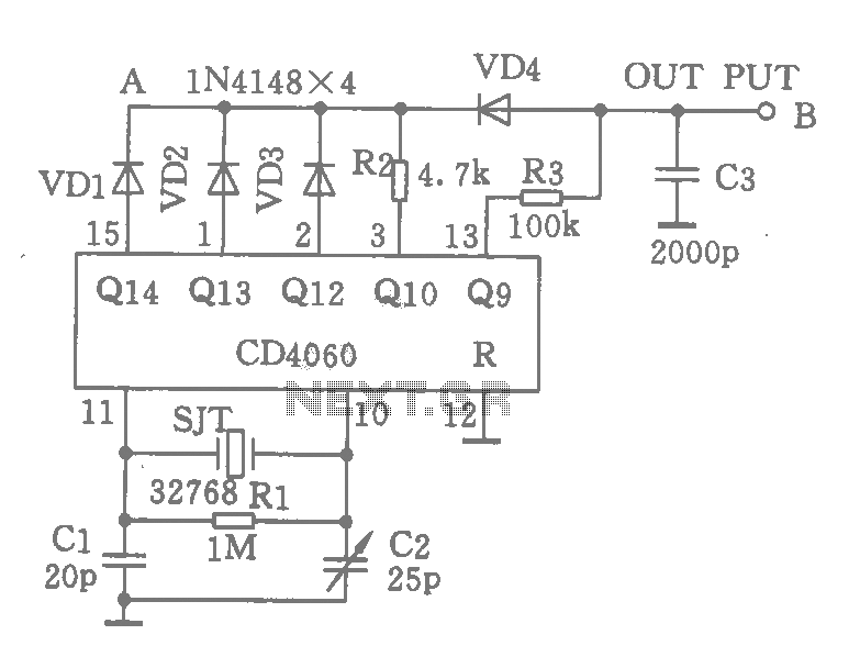
A CD4060 integrated circuit, combined with a 32,768 Hz crystal oscillator, is utilized to create a highly accurate clock source that generates 60 pulses per second. The operation is based on the division of the 32,768 Hz pulse output...
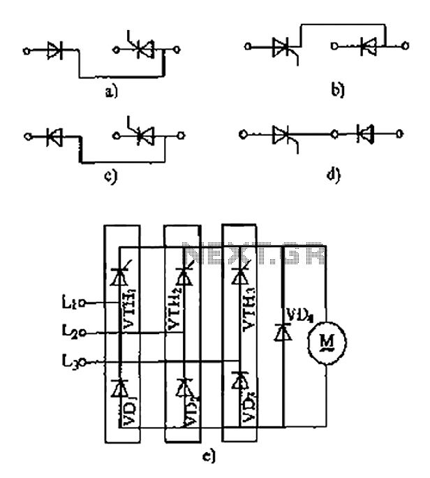
The thyristor linking arm rectifier module is a three-phase half-controlled bridge rectifier circuit. The thyristor-rectifier module linking arm consists of a thyristor and a rectifier diode connected in series or parallel, designed to fulfill specific requirements in power circuits....