
Amplifier Bridging

In a bridged amplifier configuration, two amplifier channels are combined to produce a single output that effectively doubles the voltage swing across the load. This method is commonly employed in audio amplification to increase the power output without the need for additional components, thereby maintaining a cost-effective solution. The inherent design allows for a simplified circuit path, which minimizes signal degradation and preserves audio fidelity, as no extra operational amplifiers (opamps) are introduced into the signal chain.
However, caution is advised when modifying an amplifier for bridging, particularly if the unit is still under warranty. The modification may void any existing warranty, and it is essential to ensure that the amplifier can handle the operational demands of bridging. In bridge mode, the amplifier operates as if it is driving a load with half the impedance of a standard load. For instance, when bridging a stereo amplifier designed for an 8 Ohm load, each channel effectively sees a load of 4 Ohms. This places additional strain on the amplifier, requiring it to be capable of delivering sufficient current without overheating or distorting.
Additionally, it is important to consider the turn-on and turn-off characteristics of the amplifier. Many amplifiers exhibit a small thump or pop when powered on or off, which can be more pronounced in a bridged configuration. This thump is a result of the sudden change in output voltage and can be particularly noticeable in passive loudspeakers. Therefore, it is advisable to implement a soft-start circuit or a delay circuit to mitigate this issue, ensuring a smoother transition during power cycling.
In summary, while bridging an amplifier can provide significant benefits in terms of increased output power and cost savings, careful consideration of the amplifier's specifications and potential modifications is essential to achieve optimal performance and reliability.The primary advantage of this method of bridging is that no additional components are needed (which means that it is cheap), and there is no signal degradation from additional opamps in the circuit path. The results are at least as good as using an external circuit, but you have to be prepared to modify your amplifier.
This is not a good idea if it is under warranty! There is a negative though. Most amplifiers have a small and usually almost inaudible thump at turn-on and off, and the thump is accentuated by this technique. Always remember that when an amplifier is operated in bridge mode, it appears to be driving 1/2 the normal load impedance, so make sure each channel of your stereo amp is capable of driving 4 Ohms if you are planning to operate into a standard 8 Ohm louds 🔗 External reference
Related Circuits
A very good circuit of pre-preamplifier for amplification of signals from heads of Moving Coil. It uses the two departments of tube ECC88, association parallel, for reduction of produced noise. The circuit enters in line with existing circuit PHONO....
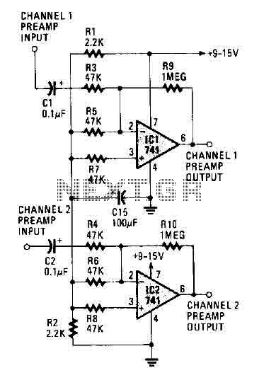
The circuit operates using two 741 operational amplifiers and achieves a gain exceeding 20 dB in each channel. Utilizing a higher-quality op-amp can improve the noise figure and bandwidth. Additionally, the circuit features a sharp roll-off at 20,000 Hertz. This...
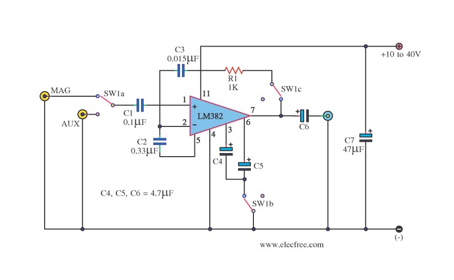
This is a simple preamplifier circuit. It can accept a general AUX sound signal as well as a signal from a microphone. The purpose of the circuit is to amplify the sound signal at the initial stage using an...
This circuit utilizes the TA7222AP to amplify audio signals. The cost is only $0.99, and it can provide 5.8 watts with muting control. The power supply can be in the range of 8-12 VDC, making it suitable for applications...
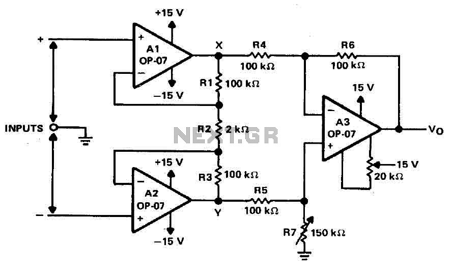
Operational amplifiers A1 and A2 are connected in a non-inverting configuration to form amplifier A3. The operational amplifier A3 can be classified as a subtractor circuit that converts the differential signal between the floating points X and Y into...
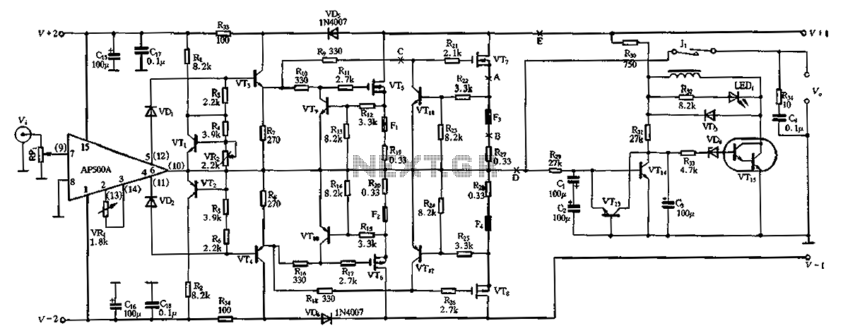
The CPI is a 100W DC super power amplifier circuit based on the AP500. It features a parallel push-pull amplifier output stage composed of transistors VT5, VT6, and VT7 to enhance output power. The circuit's output power is low...