
Amplifier Timer Circuit Schematic
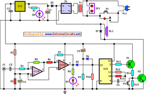
The circuit operates as a low-signal timer and power management system, suitable for applications where devices need to conserve energy by shutting down after a period of inactivity. The core of the circuit is built around the timer IC, which is configured to count the absence of an audio signal. The operational amplifiers (IC2A and IC2B) serve to enhance the input signal, ensuring that even weak audio signals can be detected effectively. The LED (D4) provides a visual indication of signal presence, which is crucial for troubleshooting and verification of the circuit's operation.
The timing mechanism is based on a capacitor (C3) that charges and discharges based on the input signal's presence. When the audio signal is detected, the capacitor is reset, preventing the timer from reaching its cutoff threshold. The two transistors (Q1 and Q2) are configured in such a way that they control the relay, allowing for the switching of higher power loads through SK1. This design ensures that the connected appliances are only powered when there is an active audio signal, thereby enhancing energy efficiency.
The inclusion of capacitor C5 and resistor R9 ensures that the timer IC (IC3) is reset upon initial power-up, providing a reliable start condition. Switch P2 offers manual control, allowing users to override the automatic shut-off feature and turn off the device at any time. This comprehensive design effectively balances automated control with user intervention, making it suitable for various audio-related applications where energy conservation is a priority.This circuit turns-off an amplifier or any other device when a low level audio signal fed to its input is absent for 15 minutes at least. Pushing P1 the device is switched-on feeding any appliance connected to SK1. Input audio signal is boosted and squared by IC2A & IC2B and monitored by LED D4. When D4 illuminates, albeit for a very short peak, I C3 is reset and restarts its counting. Pin 2 of IC3 remains in the low state, the two transistors are on and the relay operates. When, after a 15 minutes delay, no signal appeared at the input, IC3 ends its counting and pin 2 goes high. Q1 & Q2 stop conducting and the relay switches-off. The device is thus completely off as also are the appliances connected to SK1. C5 & R9 reset IC3 at power-on. P2 allows switch-off at any moment. 🔗 External reference
Related Circuits
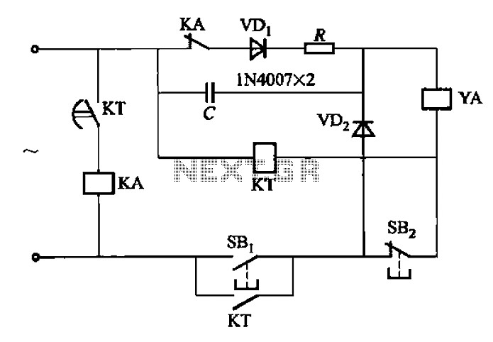
AC solenoid DC circuit operation operates similarly to a DC contactor circuit, but the AC solenoid pull circuit is illustrated in the provided figure. The capacitance C is generally between 1-10 microfarads (µF), with a minimum of 20 microfarads...
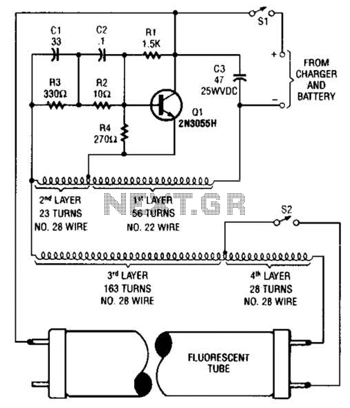
A 2N3055 oscillator (Q1) drives a homemade transformer, wound on a Vk ferrite rod. S2 is used as a filament switch and can be eliminated if desired. A 20-W fluorescent tube is recommended. The supply voltage is 12 V. The...
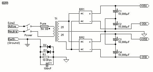
For the 60W amplifier, a nominal (full load) supply of +/- 35V is required, so a 25-0-25 secondary is ideal - however, see Updates, below. The circuit for the supply is shown below, and uses separate rectifiers, capacitors and...
This quartz crystal oscillator circuit exhibits greater stability compared to a parallel resonance circuit. It is capable of generating frequencies up to 30 MHz or even higher when utilizing BFR91 transistors for T1 and T2, along with reduced values...
This amplifier is suitable for various applications that demand high power, low noise, minimal distortion, and superior sound quality. Examples include subwoofer amplifiers, front-of-house (FOH) stage amplifiers, and individual channels of high-powered surround sound amplifiers. For a detailed explanation...
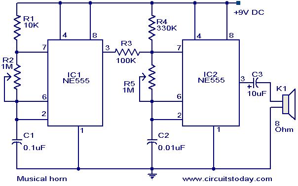
This document outlines a straightforward circuit diagram for a musical horn utilizing two NE555 integrated circuits (ICs). Both ICs are configured as astable multivibrators. The output from the first multivibrator is connected to the discharge pin (pin 7) of...