
OPTICALLY ISOLATED ANALOG MULTIPLEXER

This circuit design is particularly advantageous for applications requiring high precision and electrical isolation between the input signals and the processing circuitry. The use of the PS2501-4 optoisolator enables effective isolation, ensuring that high-voltage or noisy signals do not interfere with the sensitive analog-to-digital conversion process.
The circuit comprises three distinct input channels, each employing an LED from the optoisolator to transmit signals. The optoisolator's phototransistor receives the light emitted by the LED, allowing for the corresponding electrical signal to be transmitted to the output side. This configuration minimizes the risk of ground loops and protects the analog-to-digital converter from potential overvoltage conditions.
To implement the circuit, the 15-V power supply is connected to the anodes of the LEDs, while the cathodes are connected to the input signals. Each input signal can be selectively routed through the multiplexer, allowing for the desired channel to be activated while the others remain inactive. This selective operation is controlled by the multiplexer’s select lines, which dictate which LED is illuminated, thereby controlling the corresponding phototransistor.
The output from the phototransistors is then fed into the analog-to-digital converter, where the isolated signals can be accurately processed. This design not only enhances signal integrity but also improves the overall reliability of the data acquisition system by ensuring that the sensitive components are shielded from potentially damaging voltages present at the input stage.
In summary, this circuit design is an effective solution for applications requiring robust signal isolation and precision, leveraging the capabilities of optoisolators to maintain signal fidelity while safeguarding the analog processing components.The circuit described here provides three channels of optically isolated input that will work for many precision signal-acquisition applications. The only power required is a single 15-V rail with ground common to the analog-to-digital converter. Multiplexer operation is based on an ordinary quad-channel optoisolator (PS2501-4). Each LED (such as E1) in comb.. 🔗 External reference
Related Circuits
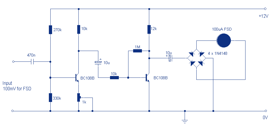
Audio levels can be monitored using a small panel meter with this circuit built from discrete components. The circuit has a flat frequency response from about 20Hz to well over 50Khz. Input sensitivity is 100mV for a full scale...
The project involves implementing analog-to-digital conversion using the ADC0804LCN 8-bit A/D converter. A circuit will be designed and programmed so that when an analog signal is input, the corresponding digital voltage is displayed on an LCD. Essentially, the circuit...
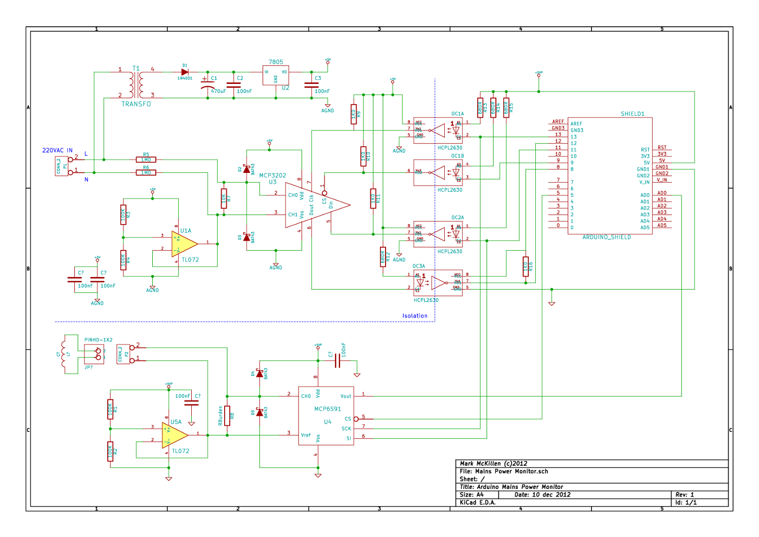
A mains (220-240VAC) power monitoring circuit has been sought for interfacing with an Arduino. While the OpenEnergyMonitor solution employs a transformer for isolation and measurement of mains voltage, it has been noted that the transformer does not couple effectively...
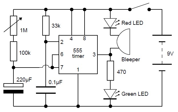
This adjustable analog timer circuit begins timing when it is activated. A green LED illuminates to indicate that the timing is in progress. Upon completion of the set time period, the green LED turns off, a red LED activates,...
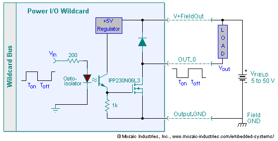
The embedded I/O board offers isolated high voltage switch inputs and eight high current, high voltage DC outputs. It utilizes optically isolated, open drain N-MOSFET transistors functioning as solid state relays (SSR) to control various resistive or inductive loads....
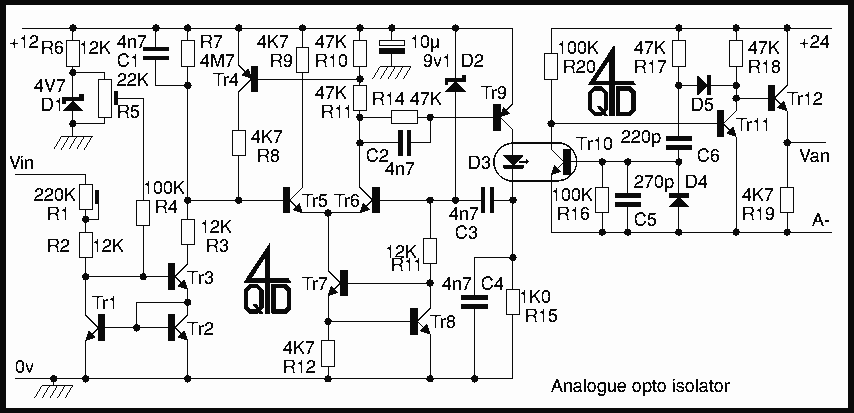
This is a circuit to use a standard, low quality opto isolator to transfer an analogue signal with reasonable linearity and without complicated feedback loops to monitor and linearise it. The circuit was designed to interface a mains driven...