
Analog Filters for Data Conversion
The process of filtering signals in electronic systems is critical for ensuring the integrity of the data being processed, particularly in applications involving analog-to-digital conversion and subsequent digital signal processing. An antialiasing filter is implemented prior to sampling to eliminate high-frequency components that could cause distortion in the digitized signal. This is particularly important in systems where accurate representation of the original signal is required. The design of the antialiasing filter must consider the sampling rate, as the Nyquist theorem dictates that the maximum frequency that can be accurately sampled is half of the sampling rate.
The reconstruction filter plays a complementary role after the digital-to-analog conversion, smoothing out the output signal to restore the original analog waveform. The design of this filter can significantly affect the quality of the reconstructed signal, particularly in applications such as audio processing, where fidelity is paramount.
The selection of filter types—Chebyshev, Butterworth, and Bessel—affects the phase and amplitude response of the system. Chebyshev filters offer a steeper roll-off and ripple in the passband, making them suitable for applications requiring sharp cut-offs. Butterworth filters provide a maximally flat frequency response in the passband, ideal for applications where a smooth response is necessary. Bessel filters, with their maximally flat group delay, are particularly useful in applications where phase linearity is critical, such as in audio and video systems.
The modified Sallen-Key topology is a versatile and widely-used circuit configuration for implementing these filters due to its simplicity and effectiveness. The ability to adjust the filter characteristics by varying the number of poles allows for tailored performance to meet specific application requirements. The precise selection of resistor and capacitor values is essential for achieving the desired cutoff frequency and filter behavior, with a recommendation for using components of 1% tolerance or better to minimize variability in performance.
In conclusion, a comprehensive understanding of both the theoretical and practical aspects of analog filters is essential for effective digital signal processing and the design of robust electronic systems. This knowledge lays the groundwork for more advanced topics in digital filter design and the implementation of software-based solutions that may replace traditional hardware filtering techniques.the input signal is processed with an electronic low-pass filter to remove all frequencies above the Nyquist frequency (one-half the sampling rate). This is done to prevent aliasing during sampling, and is correspondingly called an antialias filter. On the other end, the digitized signal is passed through a digital-to-analog converter and another low-pass filter set to the Nyquist frequency. This output filter is called a reconstruction filter, and may include the previously described frequency boost. Unfortunately, there is a serious problem with this simple model: the limitations of electronic filters can be as bad as the problems they are trying to prevent.
If your main interest is in software, you are probably thinking that you don`t need to read this section. Wrong! Even if you have vowed never to touch an oscilloscope, an understanding of the properties of analog filters is important for successful DSP.
First, the characteristics of every digitized signal you encounter will depend on what type of antialias filter was used when it was acquired. If you don`t understand the nature of the antialias filter, you cannot understand the nature of the digital signal.
Second, the future of DSP is to replace hardware with software. For example, the multirate techniques presented later in this chapter reduce the need for antialias and reconstruction filters by fancy software tricks. If you don`t understand the hardware, you cannot design software to replace it. Third, much of DSP is related to digital filter design. A common strategy is to start with an equivalent analog filter, and convert it into software. Later chapters assume you have a basic knowledge of analog filter techniques. Three types of analog filters are commonly used: Chebyshev, Butterworth, and Bessel (also called a Thompson filter).
Each of these is designed to optimize a different performance parameter. The complexity of each filter can be adjusted by selecting the number of poles, a mathematical term that will be discussed in later chapters. The more poles in a filter, the more electronics it requires, and the better it performs. Each of these names describe what the filter does, not a particular arrangement of resistors and capacitors.
For example, a six pole Bessel filter can be implemented by many different types of circuits, all of which have the same overall characteristics. For DSP purposes, the characteristics of these filters are more important than how they are constructed.
Nevertheless, we will start with a short segment on the electronic design of these filters to provide an overall framework. Figure 3-8 shows a common building block for analog filter design, the modified Sallen-Key circuit. This is named after the authors of a 1950s paper describing the technique. The circuit shown is a two pole low-pass filter that can be configured as any of the three basic types.
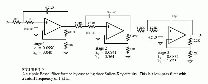
Table 3-1 provides the necessary information to select the appropriate resistors and capacitors. For example, to design a 1 kHz, 2 pole Butterworth filter, Table 3-1 provides the parameters: k1 = 0. 1592 and k2 = 0. 586. Arbitrarily selecting R1 = 10K and C = 0. 01uF (common values for op amp circuits), R and Rf can be calculated as 15. 95K and 5. 86K, respectively. Rounding these last two values to the nearest 1% standard resistors, results in R = 15. 8K and Rf = 5. 90K All of the components should be 1% precision or better. The particular op amp use isn`t critical, as long as the unity gain frequency is more than 30 to 100 times higher than the filter`s cutoff frequency.
This is an easy requirement as long as the filter`s cutoff frequency is below about 100 kHz. Bessel filter created by cascading three stages. Each stage has different values for k1 and k2 as provided by Table 3-1, resulting in different resistors and capacitors being used. Need a high-pass filter Simply swap the R and C components in the circuits (leaving Rf a 🔗 External reference
Related Circuits
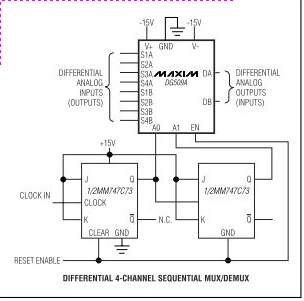
Maxim's DG508A and DG509A are monolithic CMOS analog multiplexers. The DG508A is a single 8-channel (1-of-8) multiplexer, while the DG509A is a differential 4-channel (2-of-8) multiplexer. Both devices guarantee high performance and reliability. The DG508A and DG509A analog multiplexers are...
Build an interface board to connect scientific equipment, specifically a pair of photovoltaic tubes, to a personal computer for acquiring measurement results. The signal properties include two channels with a common ground, a one-second acquisition time, and a maximum...
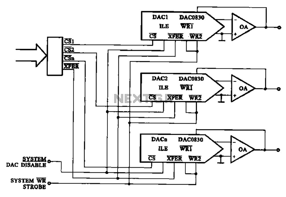
A multi-channel D/A converter circuit is presented, illustrating its fundamental structure. This circuit effectively converts encoded digital signals into multiplexed analog signal outputs. The multi-channel Digital-to-Analog (D/A) converter circuit is designed to facilitate the conversion of digital signals into corresponding...
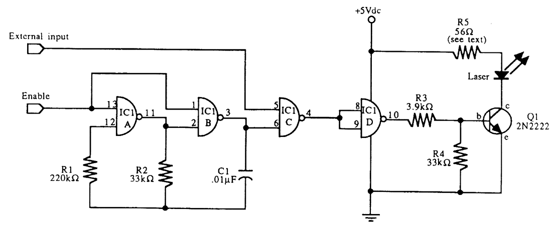
This schematic for an experimental data transmitter utilizes optical fibers and a laser diode. The transmission frequency of the free-running oscillator is approximately 3 kHz. Resistor R5 may need to be adjusted to match the specifications of the laser...
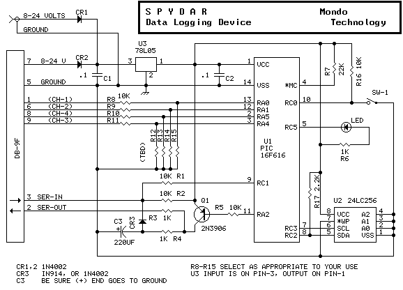
This is a circuit monitoring device. It runs for over 10 days and can log up to 32k events both digital and analog. Samples are logged either on a timing basis (0.01 to 2.5 seconds), or on a triggered...
Data acquisition is the process by which events in the real world are sampled and translated into machine-readable signals. Data acquisition typically involves sensors, transmitters and other instruments to collect signals, waveforms etc. to be processed and analyzed with...
Warning: include(partials/cookie-banner.php): Failed to open stream: Permission denied in /var/www/html/nextgr/view-circuit.php on line 713
Warning: include(): Failed opening 'partials/cookie-banner.php' for inclusion (include_path='.:/usr/share/php') in /var/www/html/nextgr/view-circuit.php on line 713