
1HZ Standard digital clock
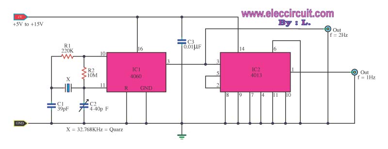
The digital clock circuit operates by utilizing the IC-4060 as a frequency divider and oscillator. The IC-4060 is capable of generating a stable clock signal, which can be adjusted to either 1 Hz or 2 Hz depending on the configuration of external components such as resistors and capacitors connected to its pins. This frequency generation is crucial for timekeeping accuracy in digital clocks.
The IC-4013, a dual D-type flip-flop, is employed to further process the clock signal from the IC-4060. The flip-flops can be configured to count the pulses generated by the IC-4060, effectively dividing the frequency to achieve the desired timekeeping functionality. By cascading multiple flip-flops, the circuit can count seconds, minutes, and hours, displaying the time in a standard digital format.
Additional components, such as a 7-segment display, can be integrated into the circuit to visually represent the time. The output from the IC-4013 can be connected to a decoder driver that translates the binary output into a format suitable for driving the display. Power supply considerations must also be taken into account, ensuring that the circuit operates within the specified voltage range for both ICs.
In summary, this digital clock circuit is a practical implementation of frequency division and counting using the IC-4060 and IC-4013, providing a reliable solution for timekeeping in various applications.This is a standard digital clock circuit,frequency size 1 Hz or 2 Hz. It can be used in the normal clock circuit. It consists of IC-4060 and IC-4013, the. 🔗 External reference
Related Circuits
The device is designed to promote respectful time management during meetings, particularly useful in ship-room or SCRUM meetings. The following is a list of components required, including links for purchasing specific parts. It is advisable to check eBay or...
This example illustrates the process of stacking layers and designing transmission lines for a high-speed digital printed circuit board (PCB). It also shows how to create a moated ground area with a bridge around a high-frequency crystal oscillator, perform...
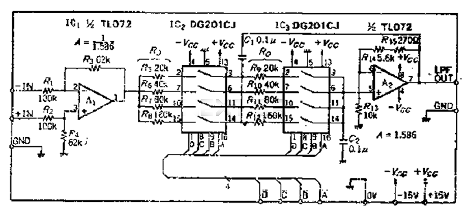
The circuit primarily consists of two Butterworth filters, designed to create a feedback amplifier with a gain of approximately 0.707. It features a differential input amplifier, where one input is grounded, resulting in a single input terminal. The attenuation...
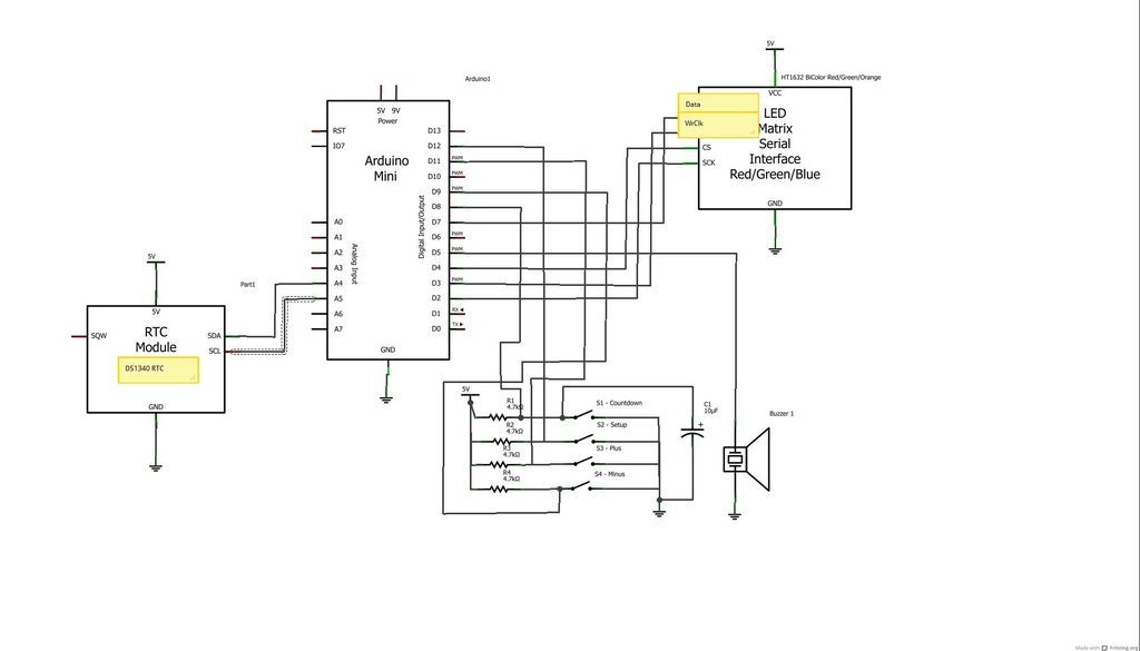
This article discusses the creation of a digital thermometer using the Arduino Uno. The temperature sensor employed is the LM35DZ, although it can be substituted with other sensors like the DS18B20. The sensor detects temperature and sends the data...
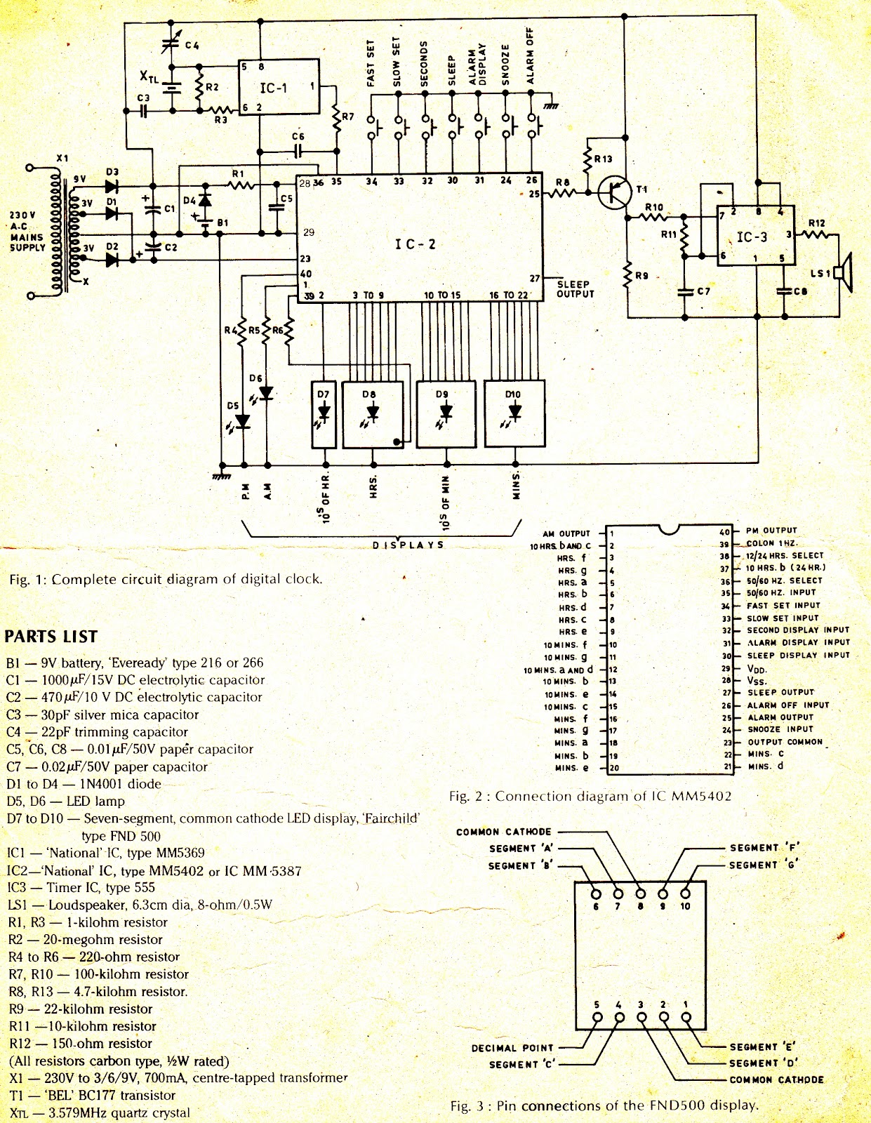
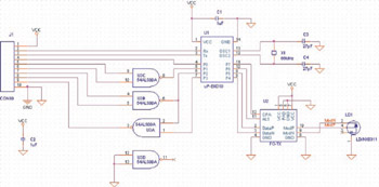
The complete circuit diagram is shown in Figure 1. The heart of the system is IC2, National's MM5402 clock chip, which is a MOS monolithic large-scale integrated circuit. Its pin configuration is illustrated in Figure 2. The supply is...
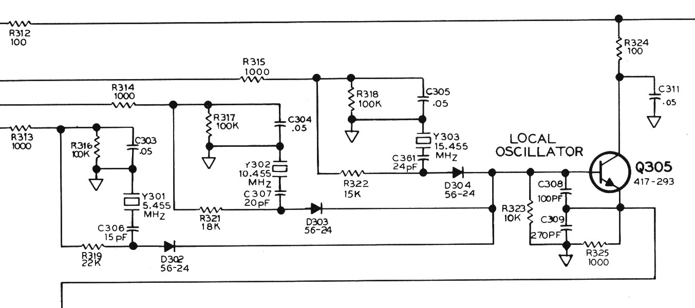
A three-channel HF receiver operates at frequencies of 5, 10, and 15 MHz, designed to receive time and frequency broadcasts from WWVH in Hawaii or the U.S., displaying time with a precision of one-tenth of a second. It features...