
Digital Clock
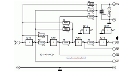
The common anode for each display is driven by the collectors of transistors Q8 to Q13. Each LED segment (a, b, c, d, e, f, g) of the display is connected in parallel and is driven by transistors Q1 to Q7, creating a multiplexing system operating at a frequency of 1kHz, determined by R3 and C3. The power supply is a standard circuit composed of T1 and GR1, along with capacitor C1. Additional capacitors (C2, C3, C4, C5) and resistor R5 provide local voltage stabilization and protect IC1 from voltage spikes. Diode D1 limits the peak rectified voltage at pin 16. Resistors R18 to R24 limit the current flowing through the LEDs.
Switch S1 has two positions: in position 2, the clock measures time, and the display remains illuminated; in position 1, the display turns off while the clock continues to operate, allowing for use in dark environments. Switch S2 allows for 12-hour or 24-hour time display selection, while S3 toggles between displaying seconds or only hours and minutes. Switches S4, S5, and S6 are used for setting the time when interruptions occur. Pin 11 (50/60Hz Select) is where the operation frequency of the MM5314N is selected; it is connected to Vss at pin 2 for 60Hz operation (110Vac) and left unconnected for 50Hz operation (220Vac). Pin 16 receives the mains frequency sample, enabling the counter circuits to measure time accurately.
Part List
R1= 100Kohms C1= 2200uF 25V D1= 1N4148
R2= 47Kohms C2= 100uF 25V GR1= 4X1N4002
R3= 100Kohms C3= 18nF 100V polyester S1...3= 1X2 mini switch
R4.....10= 2.2Kohms C4-5= 10nF ceramic or polyester S4...6= Push Button normal open
R11.....17= 10Kohms Q1....7= BC550 T1= 220V AC/12V 1A
R18.....24-25-26= 220 ohms 0W5 Q8....13= BC560 DS1....DS7= Display 7 segments Common Anode
R25-26=1.2Kohms 0W5 IC1= MM5314N ***[See Notice]The digital clock of circuit, has as base one IC, the MM5314N, in which are contained all the circuits that need. The IC1 collaborates with six Display of common anode, that are not critically as materials. You can select what dimension, you want it is enough you adapt pins their in the circuit. The display are drive by a system of polyplexis and are drive by thirteen transistors. For timing the circuit, is used the frequency of network (50HZ). This solution is the simplest, that it is not best. For more constant frequency you can use a circuit that would be based on crystal, (it will be given shortly).
For the clue of hour are used six display of 7 element common anode. The DS1-DS2, show the hours (decades-unit respectively), the DS3-DS4, show the minutes and DS5-DS6, the seconds. The common anode, for each display is drive by the collector of transistors Q8 until Q13. Individual led (a, b, c, d, e, f, g) the display, they are linked between them (parallel) and are drive by the transistors Q1.. Q7, creating thus a system multiplexing, to frequency 1KHZ, that is determined by the R3-C3. The power supply is a classic circuit, from T1 and GR1, C1. The remainder capacitors as the C2-C5 and the R5 make local unyoke of voltage and protect the IC1 from peaks of voltage.
The diode D1, limit the top, of rectified vibrations in the pin 16. Resistances R18...24, limit the current that leak the led. With switch S1 in place 2, the clock measures the time and the display remains openly, with the S1 in place 1, the display they remain closed, the clock however continues working. This operation us allows to have the clock in spaces that we do not want exists the lighting of display.
With the S2 in place 1, we have measurement in 12-hours base while in place 2, we have measurement in 24-hours base. With the S3 in place 1, we see the measurement in seconds, while in place 2, we only see the measurement in hours and minutes, while the seconds do not function.
With switches S4, S5, S6, we make the regulation of hour when exists some interruption in the operation of clock, and becomes with the classic way that usually becomes in this type the clocks. The pin 11 [ 50/60 of HZ Select ] is the input with which we select the operation of MM5314 in main voltage frequency 60HZ or 50HZ.
When we have main voltage 110Vac- 60HZ [USA system] then the pin 11 is connected in Vss @pin 2. If the main voltage is 220Vac - 50HZ [Europe system] the pin 11 is not connected nowhere, remain that is to say in air. Pin 16 [50/60 input], is the input, where is applied sample from the main voltage [50HZ or 60HZ]. With this sample function the counter circuits and become the measurement of time. Thus if you have 220Vac/50HZ, then the pin 11 remains void. If you have 110V/60HZ, then the pin 11 it's connected in Vss @ pin 2. **Notice: The MM5314N rather been withdrawn from the manufacture, likely it exist somewhere in small quantities.
I don?t have nobody information round he. Part List R1= 100Kohms C1= 2200uF 25V D1= 1N4148 R2= 47Kohms C2= 100uF 25V GR1= 4X1N4002 R3= 100Kohms C3= 18nF 100V polyester S1...3= 1X2 mini switch R4.....10= 2.2Kohms C4-5= 10nF ceramic OR polyester S4...6= Push Button normal open R11.....17= 10Kohms Q1....7= BC550 T1= 220V AC/12V 1A R18.....24-25-26= 220 ohms 0W5 Q8....13= BC560 DS1....DS7= Display 7 segmens Common Anode R25-26=1.2Kohms 0W5 IC1= MM5314N ***[See Notice] 🔗 External reference
Related Circuits
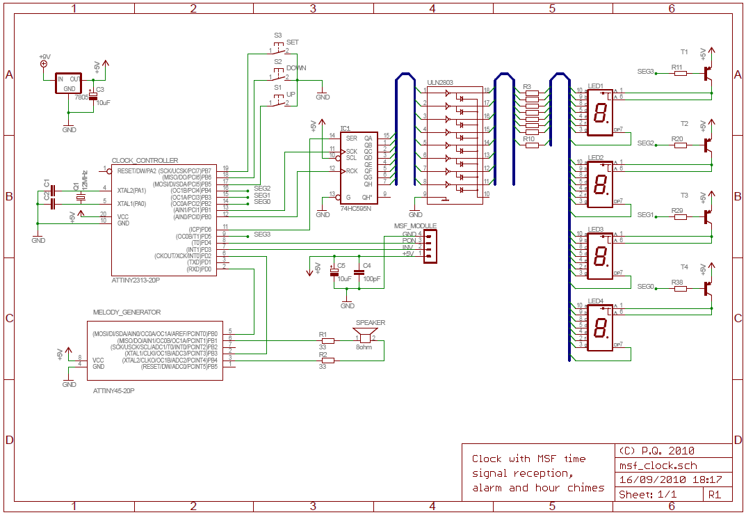
The National Physics Laboratory broadcasts a time signal, previously known as the Rugby clock but now called "Time from NPL." Its most commonly known as the MSF signal due to it originally being identified in Morse code those letters....
This circuit was designed for digital cameras, which are known to have significant power consumption. For instance, the Minolta E223 camera requires approximately 800 mA. In practice, this demand can be met using a mains power supply or high-capacity...
The operation of the converter is based on the weighted addition and transfer of the analog input levels to the digital output levels. It consists of... The converter functions by utilizing a weighted summation technique to process analog signals and...
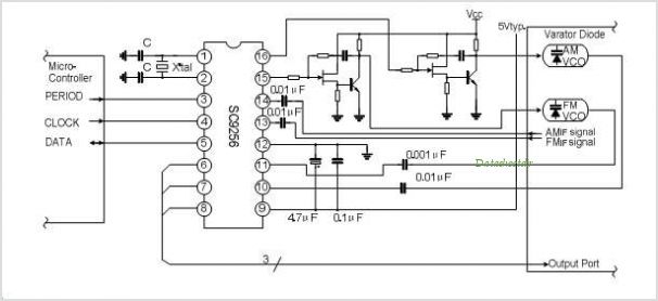
The SC9270C/SC9270D is a comprehensive DTMF receiver that integrates both bandsplit filtering and digital decoding functions. The filter section utilizes switched capacitor techniques to achieve high- and low-group filtering along with dial-tone rejection. The decoder employs digital counting techniques...

The term "mixed-signal" typically refers to circuits and integrated circuits (ICs) that process both analog and digital signals. In this context, the designation "A mixed-signal LED clock" may be somewhat misleading, as this is a fully digital clock. However,...
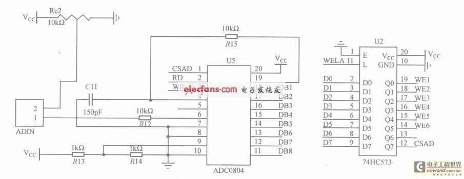
The circuit utilizes the ADC0804, which is configured for left-handed operation, alongside the 74HC573 latch, which is configured for right-handed operation. The latch is connected to a microcontroller, but they are not drawn in the same schematic. The CSAD...