
digital step km counter with
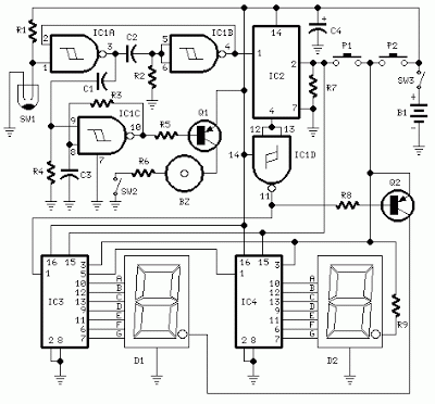
The circuit described operates as a pedometer to measure walking distance through a combination of displays and sensors. The heart of the system is a microcontroller that processes input from a mercury switch, which detects movement. The mercury switch is strategically positioned to ensure it activates with each step taken.
The leftmost display D2 is a seven-segment LED display capable of showing digits from 0 to 9, representing kilometers. The rightmost display D1 serves a similar purpose but is dedicated to the hundreds of meters, allowing for a clear distinction between kilometers and smaller distance increments. The continuous illumination of the dot on D2 serves as a visual cue for users, indicating the unit of measurement being displayed.
For auditory feedback, a beeper is incorporated into the design, providing confirmation of each counted unit. This feature can be disabled to suit the user's preference. The design accounts for the average step length of 78 centimeters, allowing the system to translate physical movement into digital distance measurements accurately.
The circuit employs a low-power design, activating the display only when necessary, which is achieved by the user pressing the pushbutton P2. This feature is essential for extending battery life, particularly in portable devices.
The reset functionality is designed with user error prevention in mind. Requiring both pushbuttons to be pressed simultaneously to reset the counters ensures that accidental resets do not occur during regular use.
Overall, while the device does not provide high precision, its design prioritizes usability and efficiency, making it suitable for casual users who wish to track their walking distances without the need for complex calibration or setup. Proper installation of the mercury switch and its angle is crucial for maintaining the accuracy of the distance measurements, highlighting the importance of careful assembly and testing during the device's initial setup.This circuit measures the distance covered during a walk. Hardware is located in a small box slipped in pants` pocket and the display is conceived in the following manner: the leftmost display D2 (the most significant digit) shows 0 to 9 Km. and its dot is always on to separate Km. from hm. The rightmost display D1 (the least significant digit) sh ows hundreds meters and its dot illuminates after every 50 meters of walking. A beeper (excludable), signals each count unit, occurring every two steps. A normal step was calculated to span around 78 centimeters, thus the LED signaling 50 meters illuminates after 64 steps (or 32 operations of the mercury switch), the display indicates 100 meters after 128 steps and so on. For low battery consumption the display illuminates only on request, pushing on P2. Accidental reset of the counters is avoided because to reset the circuit both pushbuttons must be operated together.
Obviously, this is not a precision meter, but its approximation degree was found good for this kind of device. In any case, the most critical thing to do is the correct placement of the mercury switch inside of the box and the setting of its sloping degree
🔗 External reference
Related Circuits
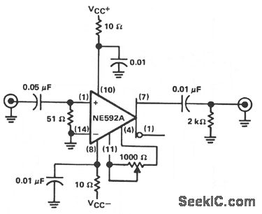
The circuit provides a voltage gain of 20 ±0.1 dB within a frequency range of 500 kHz to 50 MHz. The low-frequency response of the amplifier can be enhanced by increasing the value of the 0.05 µF capacitor connected...
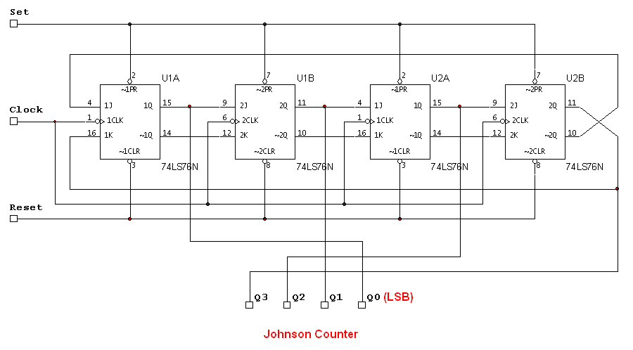
The attached schematic diagram is a Johnson Counter. Please provide advice on why "Loop 2" is considered to be invalid. Additionally, please suggest a few alternatives. The Johnson Counter, also known as a twisted ring counter, is a type of...
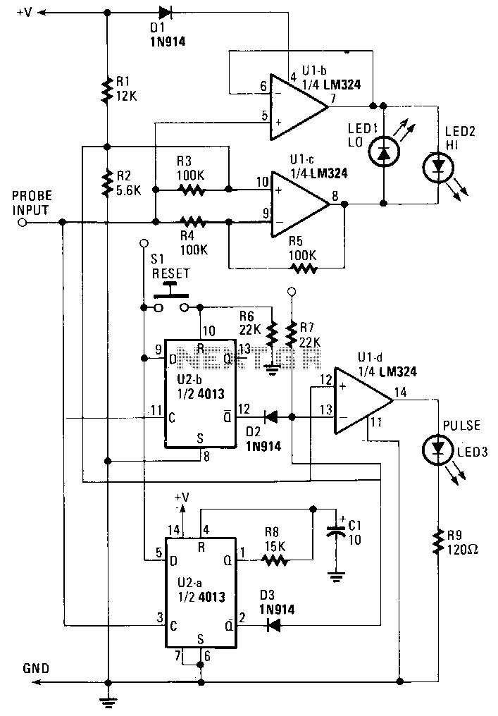
The probe operates using the power supply from the circuit under test (CUT). The input at the probe tip is divided into two pathways. One pathway directs the signal to the clock inputs of U2a and U2b. The other...
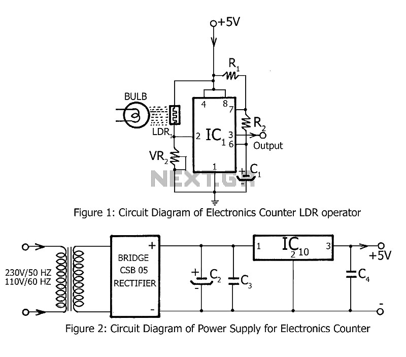
Simple counting can be performed by anyone, but counting over large intervals can be tedious and prone to errors. A previously published project, the Digital Counter, serves as a foundation for this electronics counter, which is the second project...
The circuit charges and discharges a capacitor at a crystal-controlled rate and stores the change in voltage achieved on a sample-and-difference amplifier. The current flowing during the discharge cycle is averaged and ratiometrically measured in the analog-to-digital converter (ADC)...
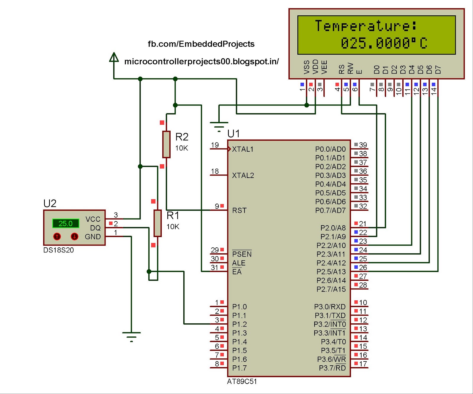
The hardware configuration for utilizing multiple 1-Wire temperature sensors, such as the DS1820, is straightforward. Communication between the microcontroller and the temperature sensors occurs over a single-wire bus, which can also supply power to the devices. An extensive number...