
thermometer dengan avr

The AVR Thermometer circuit employs a 4-digit common anode LED display, allowing for simultaneous visualization of temperature and time. The multiplexing technique used in this design ensures that each digit is activated in a sequential manner, minimizing the number of required microcontroller pins while maximizing display efficiency. The AT90S2313 microcontroller serves as the central processing unit, managing both the LED display and the DS1820 temperature sensor.
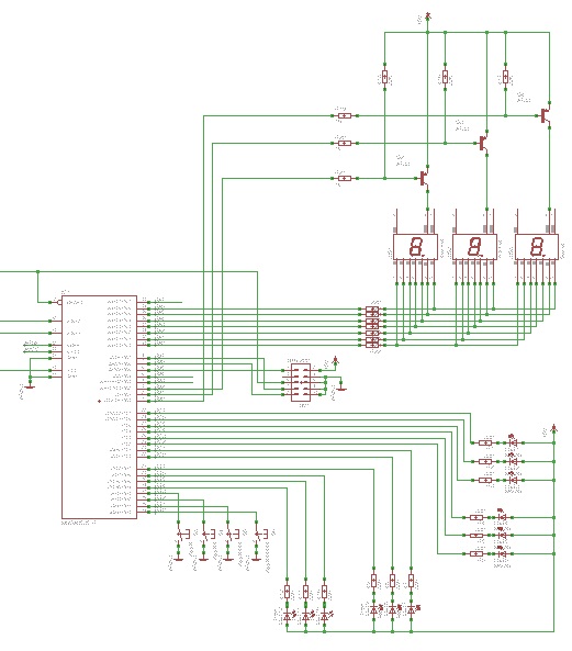
The LED segments are driven by PORTB, where each segment of the display is connected through a 220 Ohm resistor to limit current and prevent damage to the LEDs. The common anode setup requires the microcontroller to sink current, which is achieved through PORTD pins PD2 to PD5. The use of a PNP transistor allows for further control of the display, enabling more extensive interfacing options.
The DS1820 temperature sensor provides a digital temperature reading, which is connected to PD1 with a 4.7k pull-up resistor. This configuration ensures reliable communication between the sensor and the microcontroller. The program logic accommodates the potential for multiple DS1820 sensors to be connected in parallel, leveraging the unique chip ID to differentiate between sensors.
The timing mechanism in this circuit is critical for achieving accurate temperature readings and display updates. The timer0 interrupt, triggered every 1/15 seconds, allows for regular updates to the display while maintaining responsiveness to temperature changes. The use of a global variable for counting interrupts facilitates the execution of the temperature reading function at precise intervals.
Overall, this AVR Thermometer project exemplifies efficient microcontroller programming and circuit design, integrating display technology with temperature sensing to create a functional and user-friendly device. The modular nature of the design allows for future enhancements, such as additional sensors or features, making it a versatile platform for experimentation and learning in electronics.The module provide a pre wired multiplex of 4-digit common anode LED, that`s great. See the soldering pad of these signal in the 1st picture below. I thought, my friend gave me the AT90S2313 chip, and with a simple homemade ISP cableand a free software AVR ISP downloader, so we don`t need the device programmer. Also I got the DS1820 from my friend. So I spent my freetime weekend puttingthem together, "the AVR Thermometer". The 2nd picture shows a samplecircuit using universal PCB, see the upper right, it was 10-pin headerfor STK200 compatible downloader. Of course the LED module was designedfor CLOCK display, so you may interested in writing C program for bothClock and Temperature display after built this project.
The circuit diagram is straight forward, similar to 89C2051Clock Circuit. PORTB sinks forward current of each LED segmentthrough a 220 Ohms resistor. The common anode pin for each digit is controlledby PORTD, i. e. , PD2-PD5. The PNP transistor can be any types of small signaltransistor. S1-S4 are optional keypad. Also PD6 is optional output. Allof LEDs are driven with sink current. The temperature sensor chip, DS1820 is connected to PD1 with a 4. 7kpull-up resistor. The example of circuit uses only one sensor, you maytie multiple sensors on the same line and modify the program to read itwith the help of internal chip ID. The source porgram was written in C language and compiled with AVR CodeVisionC compiler. Actually my first try used the AT90S8535, then I moved theC code from 8535 to 2313 with a bit modification.
for-loop statement provides 4-cycle scanning from digit0 to digit3. First we activate digit control line by sending complement of digit variable. Follow with segment data from heat[i] array. The delay 1ms provides enoughtime for electron to jump back to ground state converting to electromagneticradiation. Then turn off before changing digit. The digit data is thenshifted to the right one bit. Similarly for the next digit. The foreground task is entered by timer0 interrupt every 1/15 s. Timer0get the internal clock from 4MHz/1024 or 3906Hz. So with an 8-bit timer0counting up from 0 to 255 and set interrupt flag from 255 to 0 transition, the rate of interrupt will be 3906Hz/256 or 15Hz.
I used a global variable "tick" for counting a number of interrupt entering. See below, when tick equal to 15 or one second has elapsed then functionread_temp() will be executed. 🔗 External reference
Related Circuits
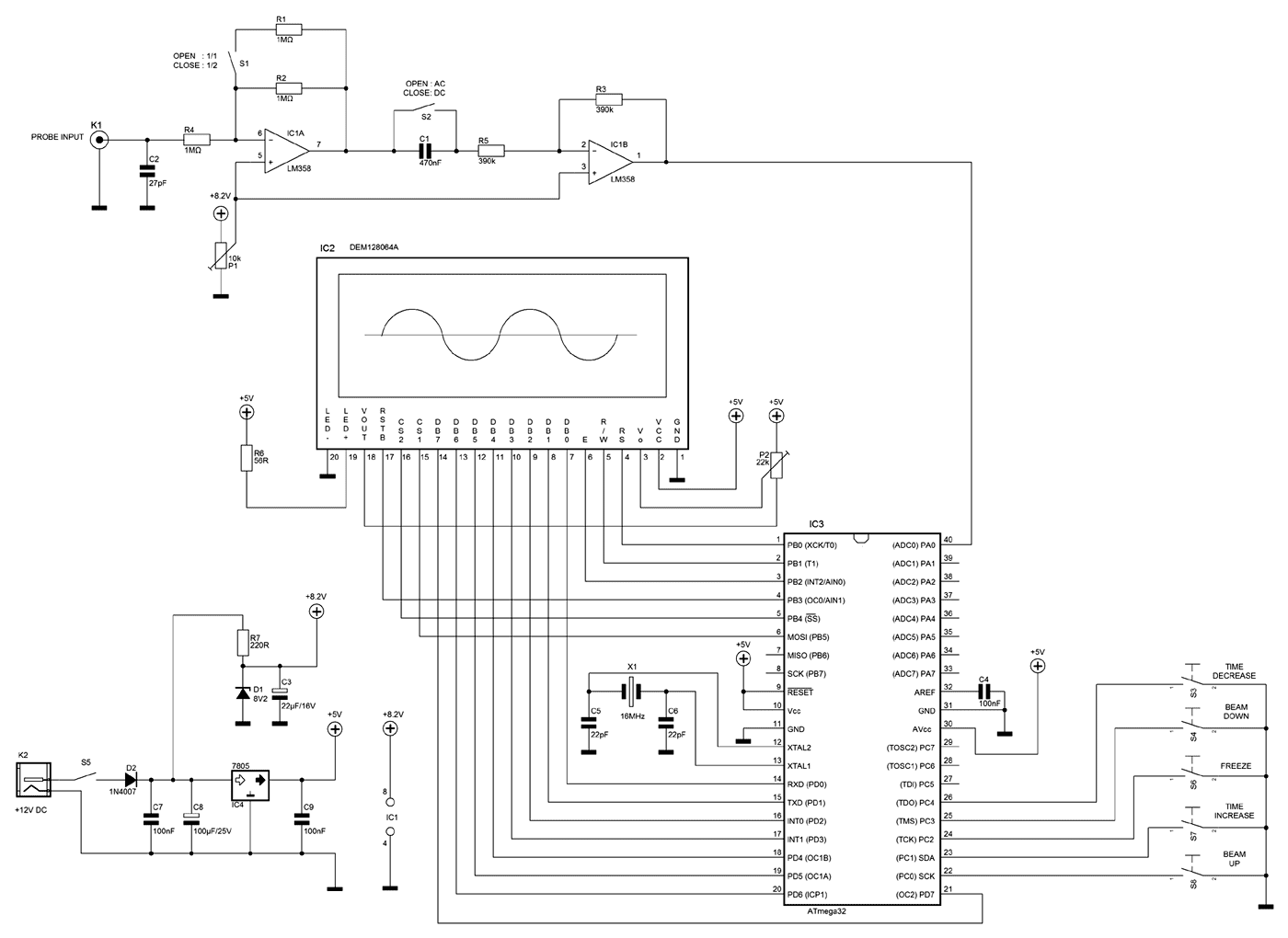
A few months ago as I was surfing on the net, I saw an oscilloscope based on PIC18F2550 microcontroller and a KS0108 controller based graphical LCD. That was Steven Cholewiak's web site. I had never seen before so amazing...

This document presents an application utilizing the Nokia 3310 LCD for designing a thermometer using the DS1621 temperature sensor IC. The DS1621 is an 8-pin sensor manufactured by Maxim. The circuit design involves integrating the DS1621 temperature sensor with a...
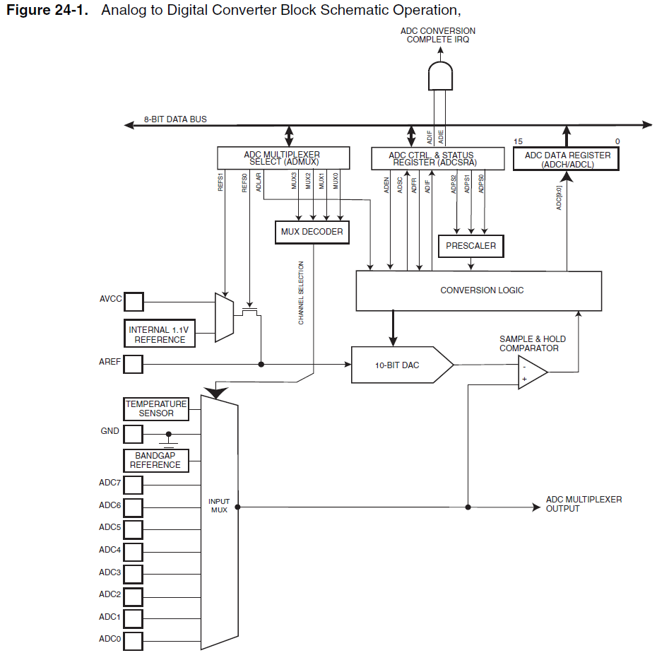
When using the internal 1.1V reference for the ADC, if the analog input exceeds 1.1V, such as 2.5V, it will not harm the microcontroller. Instead, the ADC value will clip at 0x3FF. Based on practical experience, it has been...
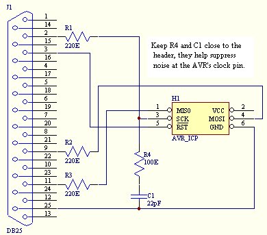
An In Circuit Programmer is a very valuable tool. Not only does it allow you to program your AVR's with ease, you can update your program without having to remove the AVR (very useful when working with surface mount...
Interface the LCD with the 8051 microcontroller AT89S52. However, upon powering up the microcontroller, the LCD displays only black boxes. Multiple codes have been tried, but the output remains the same. The circuit has been simulated in Proteus, where...
Learn to use microcontrollers to create traffic-light applications. In this project, the AVR-007 microcontroller from Circuits-Home will be utilized. Before developing the program, it is essential to understand the hardware specifications. The project focuses on developing a traffic-light control system...