
Antique Radio Dc Filament Supply Circuit
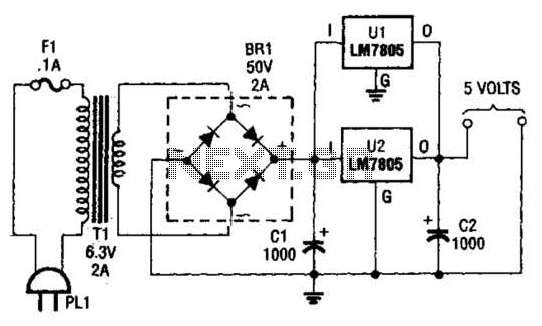
The described DC supply circuit is specifically tailored for the unique requirements of antique radios that utilize vacuum tubes, particularly those that operate on low voltage and current specifications. The circuit is engineered to deliver a stable output of 5V at a current capacity of 250 mA, which is essential for the proper functioning of the filaments in the specified tube types: 00-A, 01-A, 112A, and 71A.
The design of the DC supply incorporates several key components to ensure reliability and safety. A transformer may be used to step down the voltage from a higher AC source to a lower AC voltage, which is then rectified using a diode bridge or a single diode to convert the AC voltage to DC. Following rectification, a smoothing capacitor is employed to minimize voltage ripple, ensuring a steady DC output.
To protect the delicate tube filaments from potential overvoltage, the circuit may include a voltage regulator or a series resistor that limits the current flowing through the filaments. This is crucial, as excessive current can lead to filament burnout or reduced lifespan of the tubes. Additionally, the circuit design should account for thermal management, as the components may generate heat during operation.
Overall, this DC supply circuit provides a safe and effective means of powering antique radio tubes, preserving their functionality and extending their operational life. The careful selection of components and the attention to voltage and current specifications are paramount in maintaining the integrity of vintage audio equipment. This dc supply is great for operating battery-powered antique radios, because it is designed to prevent harming the tube filaments. The circuit is useful for powering filaments of 00-A, 01-A, 112A, and 71A tubes, which require 5V at 250 mA. 🔗 External reference
Related Circuits
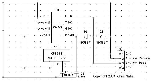
In home automation applications, there are instances where measuring the level of a body of water, such as in a pool or pond, is desired. The 1-Wire network facilitates easy interfacing of sensors to a PC or a simple...
The remote control electric hoist control circuit comprises a wireless transmitter, a wireless receiver control circuit, and a main control circuit. The wireless transmitter utilizes the TWH9326 four-key BP transmitter. The wireless receiver control circuit includes a power supply...
The circuit operates without a base current for the transistor. It turns off when the metal sheet is touched, causing the capacitor to start charging. The capacitor charges to 2V over a specified time. The circuit generates a conduction...
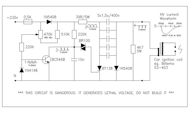
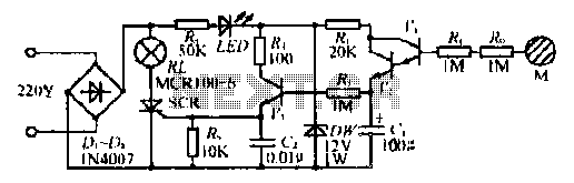
This circuit generates high voltage pulses from a 230 VAC line voltage. The drive end's swing comparator circuit was developed by the creator of this page. The working end is derived from a stroboscope trigger supply circuit. All circuits...
This schematic is provided with the intention of being useful, but it comes without any warranty, including implied warranties of merchantability or fitness for a particular purpose. The address bus in this schematic is connected in a unique manner,...
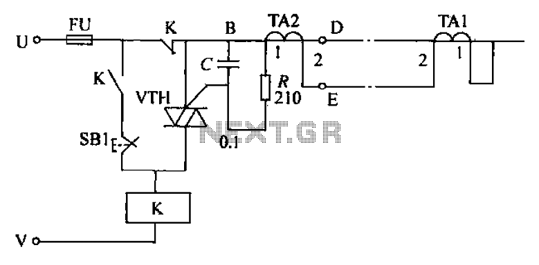
The circuit's current exceeds the load carried by the rated current meter, prompting the user to immediately cut off the power supply to address the overload. Pressing the reset button restores power, making the system simple, convenient, and practical....
Warning: include(partials/cookie-banner.php): Failed to open stream: Permission denied in /var/www/html/nextgr/view-circuit.php on line 713
Warning: include(): Failed opening 'partials/cookie-banner.php' for inclusion (include_path='.:/usr/share/php') in /var/www/html/nextgr/view-circuit.php on line 713